NetUP LLC | +1 (516) 734-0891 | info@netup.tv

Product Introduction
Outline
NetUP Streamer Base DVB4xC is a modular digital television head-end processor. The 1U chassis carries six independent module slots, and each slot is populated according to the task at hand: encoding, decoding, transcoding, multiplexing, descrambling or modulation. Because the modules are chosen per installation, a single chassis covers a wide range of input and output interfaces and signal formats.
Programs received or encoded by the modules are passed to the chassis, combined into the required transport streams and delivered to the RF, ASI and IP outputs. The device is managed entirely over the network through the web interface; there is no local display or keypad.
Main Features
-
Modular design: 1U chassis with six slots, freely combined by module type.
-
Encoding, decoding, transcoding, multiplexing, descrambling and modulation in one chassis.
-
One ASI output, mirroring MPTS 2 of the GE2 port.
-
Two GE outputs: up to 512 SPTS over UDP and RTP/RTSP from GE1, up to 8 MPTS over UDP and RTP from GE2; unicast and multicast; RJ45 or SFP.
-
Redundant power supply available on request, with or without hot-swap.
-
Web management and firmware upgrade over the network.
Chassis Variants
The chassis is supplied in two variants that differ in how transport streams are handled. Unless stated otherwise, this manual describes the base variant.
| Parameter | Base variant | Variant A |
|---|---|---|
IP data transport |
One-way: GE1 and GE2 are outputs (up to 8 MPTS and 512 SPTS) |
Bi-directional: GE1 and GE2 carry IP input and output |
Transport streams per module |
One TS (MPTS or SPTS) from each module, up to 350 Mbps |
Up to 512 TS (MPTS or SPTS) from each module, up to 350 Mbps |
Multiplexing |
Supported: streams from different modules are multiplexed into a single TS and sent out through one module or through GE1/GE2 |
Not supported: streams from different modules are combined and sent out through one module or through GE1/GE2 without remultiplexing |
Output per module |
One MPTS after multiplexing |
One or several MPTS/SPTS |
Specifications
| Parameter | Value |
|---|---|
Module slots |
6, any combination of module types |
ASI output |
1 (mirror of MPTS 2 on GE2) |
IP output |
GE1 — up to 512 SPTS over UDP, RTP/RTSP; GE2 — up to 8 MPTS over UDP, RTP; unicast and multicast |
GE interfaces |
RJ45 and SFP |
Management |
Web interface, firmware upgrade over the network |
Dimensions (W×L×H) |
482 × 410 × 44 mm |
Operating / storage temperature |
0…+45 °C (operating); −20…+80 °C (storage) |
Power |
AC 110 V ±10%, 50/60 Hz; AC 220 V ±10%, 50/60 Hz |
Redundant power supply |
Optional, with or without hot-swap |
Appearance and Illustration
Front panel:
| Element | Description |
|---|---|
ASI OUT |
ASI transport stream output; carries the same programs as MPTS 2 |
Reset |
Restores the management IP address to the factory default |
Power |
Power indicator |
Run 1–6 |
Per-slot status indicators; green means the transport stream of the module is normal |
Alarm 1–6 |
Per-slot fault indicators |
GE1 / GE2 (SFP) |
IP output, optical connectors |
GE1 / GE2 (RJ45) |
IP output, electrical connectors |
NMS |
Network management interface; the web interface is reached at this address |
CAS |
Conditional access system communication interface |
Rear panel:

The rear panel is formed by the installed modules themselves, so its appearance depends on the chosen configuration. The illustration shows one possible combination; the power inlet, power switch and grounding screw are always on the left.
Modules
Up to six modules are installed in one chassis and may be mixed and matched freely; module positions are interchangeable. Each module is ordered separately. The sections below list the module types together with the appearance of their rear panels.

|
Module rear panels are shown to help identify the interfaces. The full ordering information is available from NetUP technical support. |
Overview
| Module | Inputs | Outputs | Notes |
|---|---|---|---|
Encoding |
|||
M-ENC-4AV |
4× CVBS (DB9) or 4× SDI (BNC) |
to chassis |
MPEG-2 / H.264, SD |
M-ENC-4UHD |
4× HDMI or 4× SDI |
to chassis |
H.265 / H.264, up to 4K |
M-ENC-4HDMI |
4× HDMI |
to chassis |
H.265 / H.264, HD |
M-ENC-4CVBS |
4× CVBS + 4× stereo (DB9) |
to chassis |
MPEG-2, SD |
M-ENC-8CVBS |
8× CVBS + 8× stereo (DB15) |
to chassis |
H.264, SD |
M-ENC-2HDMI |
2× HDMI + 2× BNC (CC) |
to chassis |
Encoder or transcoder |
M-ENC-2SDI |
2× HD-SDI |
to chassis |
Encoder or transcoder |
Tuner and descrambling |
|||
M-2S2CI |
2× DVB-S/S2/S2X (F-type) |
1 MPTS to chassis |
2 CI slots, BISS |
M-4TC2CI |
4× DVB-C / J.83B / DVB-T/T2 / ISDB-T |
1 MPTS to chassis |
2 CI slots, BISS with 32 keys |
M-4S |
4× DVB-S/S2/S2X (F-type) |
1 MPTS to chassis |
Free-to-air |
M-4TC |
4× DVB-C / J.83B / DVB-T/T2 / ISDB-T |
1 MPTS to chassis |
Free-to-air |
Multiplexing and switching |
|||
M-MUX-4ASI |
4× ASI (bi-directional), 2× GE with 256 IP each |
4× ASI, IP |
Multiplexing |
M-MUX-EAS4 |
1× ASI (alert source), 256 IP via GE1 |
4× IP, up to 16 programs each |
Emergency alert |
M-MUX-EAS8 |
1× ASI (alert source), 256 IP via GE1 |
8× IP, up to 8 programs each |
Emergency alert |
M-MUX-5ASI |
5× ASI (bi-directional) |
5× ASI |
Multiplexing |
M-MUX-IP |
IP |
IP |
Demultiplexing |
M-SCR-ASI |
ASI, IP |
ASI, IP |
Scrambling, up to 4 simulcrypt CA |
M-SW-3ASI |
3× ASI |
2× ASI (mirrored) |
Transport stream switching |
Modulation |
|||
M-MOD-16C |
512 IP + stream connector |
16 carriers + 16 IP |
DVB-C, up to 4 simulcrypt CA |
M-MOD-32C |
1024 IP + stream connector |
32 carriers + 32 IP |
DVB-C, up to 4 simulcrypt CA |
M-MOD-48C |
1024 IP |
48 carriers on 2 RF ports + 48 IP |
DVB-C, up to 6 simulcrypt CA |
M-MOD-8T |
Stream connector |
8 carriers + 8 IP |
DVB-T |
M-MOD-8A |
Stream connector |
8 carriers + 8 IP |
ATSC |
M-MOD-6I |
32 IP per channel + stream connector |
6 carriers + 6 IP |
ISDB-Tb |
Decoding and transcoding |
|||
M-DEC-2SDI |
2× ASI (bi-directional) |
2× SDI |
Decodes 2 programs simultaneously |
M-DEC-4HDMI |
8 IP (MPTS/SPTS) via stream connector |
4× HDMI |
— |
M-TRX-2IP |
Stream connector |
Stream connector |
2-channel video and audio transcoding |
The sections below describe each group in detail.
Encoding Modules
NetUP Streamer Base M-ENC-4AV — 4 CVBS or 4 SDI inputs
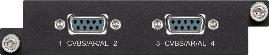
CVBS version — four CVBS inputs on a DB9 breakout |

SDI version — four SDI inputs on BNC connectors |
Four CVBS inputs (DB9 to RCA breakout) or four SDI inputs (BNC), MPEG-2 and MPEG-4 AVC/H.264, standard definition. Input 720×576@50i or 720×480@60i; the output resolution can be scaled down to 160×90. Rate control CBR/VBR; GOP structure IPPP, IBPBP, IBBPB, IBBBP; video bit rate 0.5–5 Mbps. Audio: MPEG-1 Layer 2, LC-AAC, HE-AAC; 48 kHz; 48–384 kbps per channel. Logo, caption and QR code insertion are supported.
NetUP Streamer Base M-ENC-4UHD — 4 HDMI/SDI inputs, up to 4K
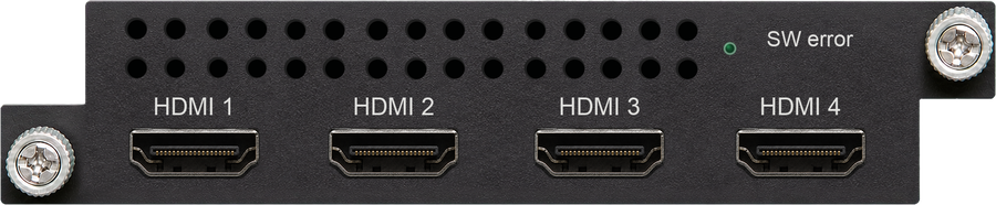
HDMI version — four HDMI inputs |
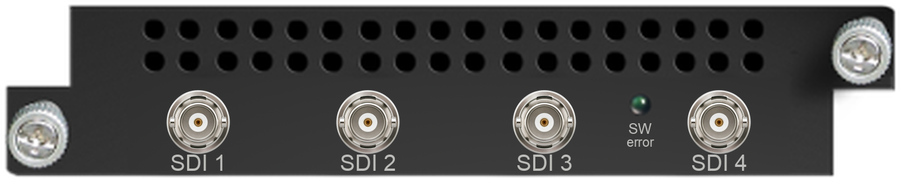
SDI version — four SDI inputs |
Four HDMI (1.4, HDCP 1.4) or SDI inputs with HEVC/H.265 and MPEG-4 AVC/H.264 encoding. Resolutions: 3840×2160_30P/29.97P (two channels per module with H.265, one with H.264), 1920×1080_60/59.94/50P (four channels with H.265, two with H.264), 1280×720_60/59.94/50P (four channels with either codec). Interlaced 1920×1080 input is encoded as progressive output. Chroma 4:2:0; bit rate 0.5–20 Mbps per channel; CBR/VBR; GOP IBBP, IPPP. Audio: MPEG-1 Layer 2, LC-AAC, HE-AAC, HE-AAC v2, AC3 pass-through; 48 kHz; audio gain 0–255.
NetUP Streamer Base M-ENC-4HDMI — 4 HDMI inputs
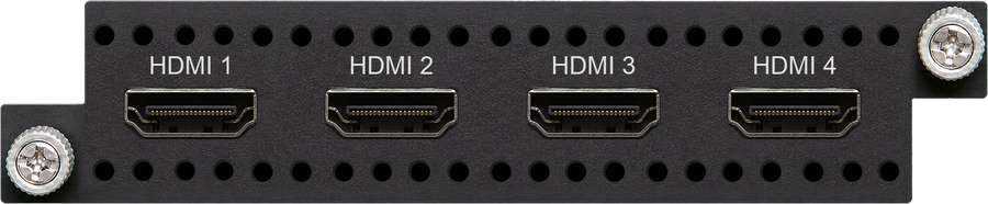
Four HDMI (1.4, HDCP 1.4) inputs with HEVC/H.265 and MPEG-4 AVC/H.264 encoding; an H.265-only version is available. Resolutions 1920×1080_60/59.94/50P and 1280×720_60/59.94/50P; interlaced input is encoded as progressive output. Chroma 4:2:0; bit rate 0.5–20 Mbps per channel with H.265 and 4–20 Mbps with H.264; CBR/VBR; GOP IBBP, IPPP. Audio as for M-ENC-4UHD. Logo and QR code insertion are available as an order option.
NetUP Streamer Base M-ENC-4CVBS — 4 CVBS inputs
Four CVBS video inputs and four stereo audio inputs (DB9 to RCA breakout), MPEG-2 encoding, 4:2:0. PAL and NTSC standard-definition signals; input resolutions from 720×576_50i and 720×480_60i down to 176×144_50i. GOP structure IP, IBP, IBBP, IBBBP; video bit rate 0.5–8 Mbps per channel; closed captions supported. Audio: MPEG-1 Layer 2 and Dolby Digital AC3 (2.0); 48 kHz, 24-bit; 128–384 kbps per channel. Logo, caption and QR code insertion are supported on one version of the module.
NetUP Streamer Base M-ENC-8CVBS — 8 CVBS inputs

Eight CVBS video inputs and eight stereo audio inputs (DB15 to RCA breakout), MPEG-4 AVC/H.264 encoding. PAL and NTSC standard-definition signals, 720×576i and 720×480i; CBR/VBR; GOP structure IPP; video bit rate 1–7 Mbps per channel. Audio: MPEG-1 Layer 2; 48 kHz, 24-bit; 64–384 kbps per channel. Logo, caption and QR code insertion are supported.
NetUP Streamer Base M-ENC-2HDMI — 2 HDMI inputs, encoding and transcoding
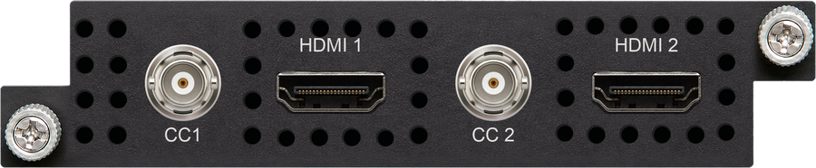
Two HDMI inputs and two BNC inputs for closed captions, plus the internal stream connector. MPEG-2 and MPEG-4 AVC/H.264 encoding; input 1920×1080_60P/50P, 1920×1080_60i/50i, 1280×720_60p/50P, 720×480_60i, 720×576_50i. CBR/VBR; aspect ratio 16:9 or 4:3; video bit rate 0.8–19 Mbps. Audio: MPEG-1 Layer II, MPEG-2 AAC, MPEG-4 AAC, Dolby Digital AC3 (2.0) encoding as an option, AC3 (2.0/5.1) pass-through; 48 kHz; 64–320 kbps per channel. Transcoding: two HD services from MPEG-2 or H.264 to MPEG-2 or H.264 (HD or SD), or four SD services; audio transcoding between MPEG-1 Layer 2, AAC and AC3 in any direction.
NetUP Streamer Base M-ENC-2SDI — 2 HD-SDI inputs, encoding and transcoding

Two HD-SDI inputs and the internal stream connector. Encoding, transcoding and audio parameters match M-ENC-2HDMI.
Tuner and Descrambling Modules
NetUP Streamer Base M-2S2CI — 2 DVB-S/S2/S2X inputs + 2 CI

Two tuner inputs (F-type) and two independent CI slots; one MPTS is passed to the chassis for remultiplexing. DVB-S, DVB-S2 and DVB-S2X; input 950–2150 MHz; symbol rate up to 45 Msps (up to 40 Msps for 8APSK and 32APSK); signal level −65…−25 dBm; DiSEqC supported. Up to 256 output PIDs with automatic or manual PID remapping, accurate PCR adjustment and automatic PSI/SI generation. Descrambling: two CAM/CI modules, and BISS Mode 1 / Mode E up to 120 Mbps as an order option.
NetUP Streamer Base M-4TC2CI — 4 DVB-C/T/T2/ISDB-T inputs + 2 CI
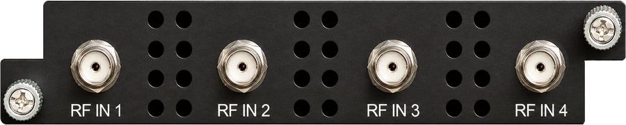
Four frequencies (each RF input locks two frequencies), F-type, with two independent CI slots; one MPTS is passed to the chassis for remultiplexing. Switchable between DVB-C (J.83 A/C), J.83B, DVB-T, DVB-T2 and ISDB-T. DVB-C: 60–890 MHz, symbol rate 1000–9000 ksps, 16/32/64/128/256-QAM (64/256-QAM for J.83B). DVB-T/T2: 60–890 MHz, bandwidth 5/6/7/8 MHz, PLP supported for DVB-T2. Up to 256 output PIDs; descrambling with two CAM/CI modules and BISS Mode 1 / Mode E with 32 keys.
NetUP Streamer Base M-4S — 4 DVB-S/S2/S2X inputs, FTA

Four tuner inputs (F-type) for free-to-air reception; one MPTS is passed to the chassis for remultiplexing. DVB-S, DVB-S2 and DVB-S2X; input 950–2150 MHz; symbol rate up to 45 Msps; signal level −65…−25 dBm; DiSEqC supported. Up to 256 output PIDs with PID remapping, accurate PCR adjustment and automatic PSI/SI generation.
NetUP Streamer Base M-4TC — 4 DVB-C/T/T2/ISDB-T inputs, FTA
Four tuner inputs (F-type) for free-to-air reception, switchable between DVB-C (J.83 A/C), J.83B, DVB-T, DVB-T2 and ISDB-T; input 60–890 MHz. The module has no output ports of its own and is always used together with another module.
Multiplexing and Switching Modules
NetUP Streamer Base M-MUX-4ASI — 4 ASI + 2 GE multiplexer
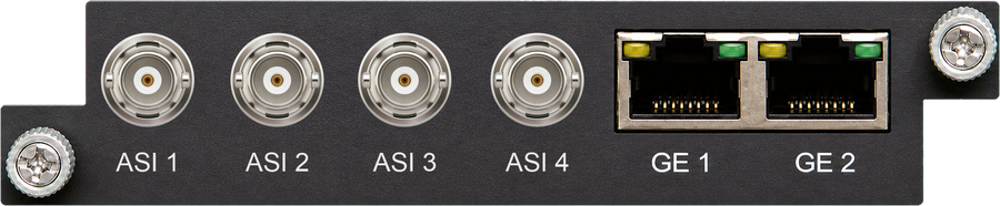
Four bi-directional ASI ports, each configurable as an input or an output, and two GE ports supporting 256 IP inputs each.
NetUP Streamer Base M-MUX-EAS4 / M-MUX-EAS8 — emergency alert multiplexer
One ASI input used as the emergency alert source and 256 IP inputs through the GE1 port (100/1000M). M-MUX-EAS4 provides four IP outputs with up to 16 programs each; M-MUX-EAS8 provides eight IP outputs with up to 8 programs each. The alert source may be the ASI input or the 256th IP input; both must be SPTS and cannot be multiplexed.
NetUP Streamer Base M-MUX-5ASI — 5 ASI multiplexer
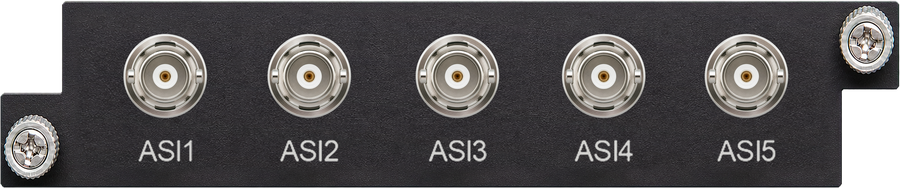
Five bi-directional ASI ports, each configurable as an input or an output.
NetUP Streamer Base M-MUX-IP — IP demultiplexer
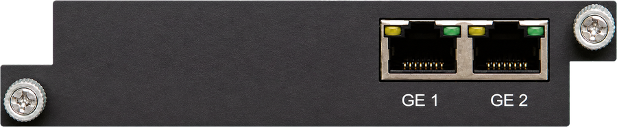
Demultiplexes IP transport streams received by the chassis.
NetUP Streamer Base M-SCR-ASI — ASI/IP multiplexer-scrambler
Multiplexing with scrambling for up to four simulcrypt CA systems, compliant with ETR 289, ETSI TS 101 197 and ETSI TS 103 197.
NetUP Streamer Base M-SW-3ASI — ASI transport stream switch
Three ASI inputs and two mirrored ASI outputs for transport stream switching.
Modulating Modules
NetUP Streamer Base M-MOD-16C / M-MOD-32C — 16 or 32 DVB-C carriers
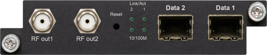
Data input: 512 or 1024 IP inputs over UDP and RTP, unicast and multicast, through two GE ports (RJ45 or SFP), plus the internal stream connector. Data output: 16 or 32 IP outputs over UDP, RTP/RTSP. RF output: 16 or 32 channels of multiplexing, scrambling and modulation. Scrambling for up to four simulcrypt CA systems (ETR 289, ETSI TS 101 197, ETSI TS 103 197). Modulation to EN 300 429 / ITU-T J.83 A/B/C; MER ≥ 40 dB; RF 50–960 MHz with 1 kHz step; symbol rate 3600–7000 ksps. Constellations: J.83A — 16/32/64/128/256-QAM, 8 MHz; J.83B and J.83C — 64/256-QAM, 6 MHz. Up to 256 output PIDs per channel.
NetUP Streamer Base M-MOD-48C — 48 DVB-C carriers

Data input: 1024 IP inputs over UDP and RTP through two GE ports (RJ45 or SFP). Data output: 48 IP outputs over UDP, RTP/RTSP; up to 840 Mbps per GE port; GE1 carries outputs 1–24 and GE2 outputs 25–48. RF output: two F-type ports for 48 non-adjacent carriers, 75 Ω; carriers 1–24 through RF1 and 25–48 through RF2, each port covering 384 MHz. Scrambling for up to six simulcrypt CA systems. Modulation, MER, frequency range and constellations as for M-MOD-16C / M-MOD-32C.
NetUP Streamer Base M-MOD-8T — 8 DVB-T carriers
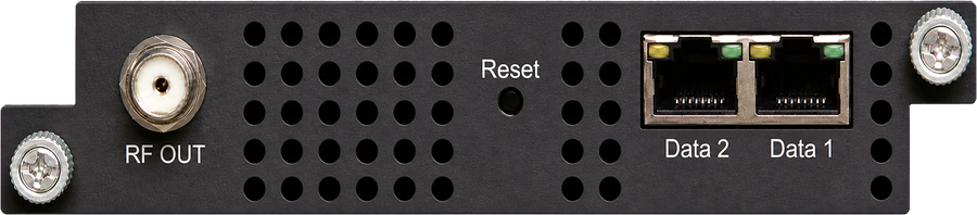
Eight DVB-T carriers, modulation to ETSI EN 300 744; MER ≥ 40 dB. Data output: 8 IP outputs over UDP, RTP/RTSP through two GE ports.
NetUP Streamer Base M-MOD-8A — 8 ATSC carriers
Eight ATSC carriers; the module is otherwise identical to M-MOD-8T.
NetUP Streamer Base M-MOD-6I — 6 ISDB-Tb carriers
Data input: up to 32 IP inputs per channel over UDP and RTP through two GE ports (RJ45 or SFP), plus the internal stream connector. Data output: 6 IP outputs over UDP, RTP/RTSP. RF output: six channels of multiplexing and modulation.
Decoding and Transcoding Modules
NetUP Streamer Base M-DEC-2SDI — 2 HD-SDI decoder
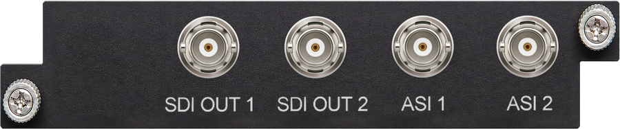
Two ASI ports, each configurable as an input or an output, and two SDI outputs. The module decodes up to two programs simultaneously.
NetUP Streamer Base M-DEC-4HDMI — 4 HDMI decoder
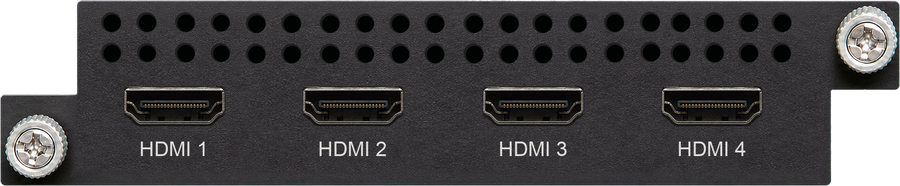
Eight IP inputs (MPTS or SPTS) over UDP through the internal stream connector, and four HDMI outputs.
NetUP Streamer Base M-TRX-2IP — 2-channel IP transcoder
Video and audio transcoding on two channels. The module has no input or output ports of its own and is always used together with another module; streams are exchanged through the internal stream connector.
Installation Guide
Acquisition Check
When unpacking the device, check the contents against the packing list. The package should normally include:
-
Head-end processor
-
Power cord
If any item is missing or does not match the list, contact your local dealer.
Installation Preparation
Follow the steps below when installing the device. This chapter covers:
-
checking the device for missing parts or transport damage;
-
preparing the installation environment;
-
installing the head-end processor;
-
connecting signal cables;
-
connecting the communication port (if required).
Environment Requirements
| Item | Requirement |
|---|---|
Machine hall space |
When installing a machine-frame array in a single hall, the distance between two rows of frames should be 1.2–1.5 m, and the distance to the wall no less than 0.8 m. |
Machine hall floor |
Electrically isolated and dust-free. Volume resistivity of the anti-static floor material: 1×10⁷–1×10¹⁰ Ω; grounding current-limiting resistance: 1 MΩ. Floor load capacity should exceed 450 kg/m². |
Ambient temperature |
5–40 °C (sustained), 0–45 °C (short term); installing air conditioning is recommended. |
Relative humidity |
20%–80% sustained, 10%–90% short term. |
Pressure |
86–105 kPa |
Doors and windows |
Install rubber strips to seal door gaps and double-glazed windows. |
Walls |
May be covered with wallpaper or low-gloss paint. |
Fire protection |
Fire-alarm system and extinguisher. |
Power |
Device power, air-conditioning power and lighting power must be independent of each other. The device requires AC 220 V ±10% or AC 110 V ±10%, 50/60 Hz. Check carefully before powering on. |
Grounding Requirements
-
Good grounding of all modules is the basis of device reliability and stability and the most important safeguard against lightning and interference. The system must follow this rule.
-
The outer conductor and isolation layer of the coaxial cable should maintain proper electrical contact with the metal housing of the device.
-
The grounding conductor must be a copper conductor to reduce high-frequency impedance; the grounding wire must be as thick and short as possible.
-
Both ends of the grounding wire must be well connected electrically and protected against rust.
-
Using any other device as part of the grounding circuit is prohibited.
-
The contact area between the grounding wire and the device frame must be no less than 25 mm².
For frame grounding, connect all machine frames to a protective copper strip. Keep the grounding wire as short as possible and avoid loops; the contact area between the grounding wire and the grounding strip must be no less than 25 mm². For device grounding, connect the device’s grounding rod to the frame’s grounding pole with a copper wire.
Wiring Connection
The power socket is located on the right of the rear panel and the power switch on the left of the front panel. Insert one end of the power cord into the socket and the other end into the AC mains.
When the device is connected to protective ground on its own, use an independent connection. When grounding is shared with other devices, the grounding resistance must be less than 1 Ω.

|
Before connecting the power cord to the device, set the power switch to "OFF". |
Signal cables are connected to the modules installed in the chassis; refer to the module rear panels in the previous chapter. The management computer is connected to the NMS port on the front panel.
Web NMS Operation
The device is configured entirely from the web interface; there is no local display or keypad. Connect the management computer to the NMS port on the front panel.
Login
The factory default IP address is 192.168.0.136.
-
Connect the computer and the device with a network cable and use the
pingcommand to confirm that they are on the same network segment. -
If the computer IP address is, for example, 192.168.0.252, set the device IP to 192.168.0.xxx (xxx can be 0 to 255, except 252, to avoid an IP conflict).
-
Enter the device IP address in the browser address bar and press Enter.
-
On the login screen, enter the user name and password (default user name
admin, passwordadmin) and press LOGIN.
If the management IP address is unknown or has been lost, press the Reset button on the front panel to restore it to the factory default.
Status
After login the "Status" page shows the state of the device: software, hardware, web and system versions, product ID and uptime, followed by the module information. The module diagram reflects the modules actually installed, and the indicators below it show the Run and Alarm state of each slot.
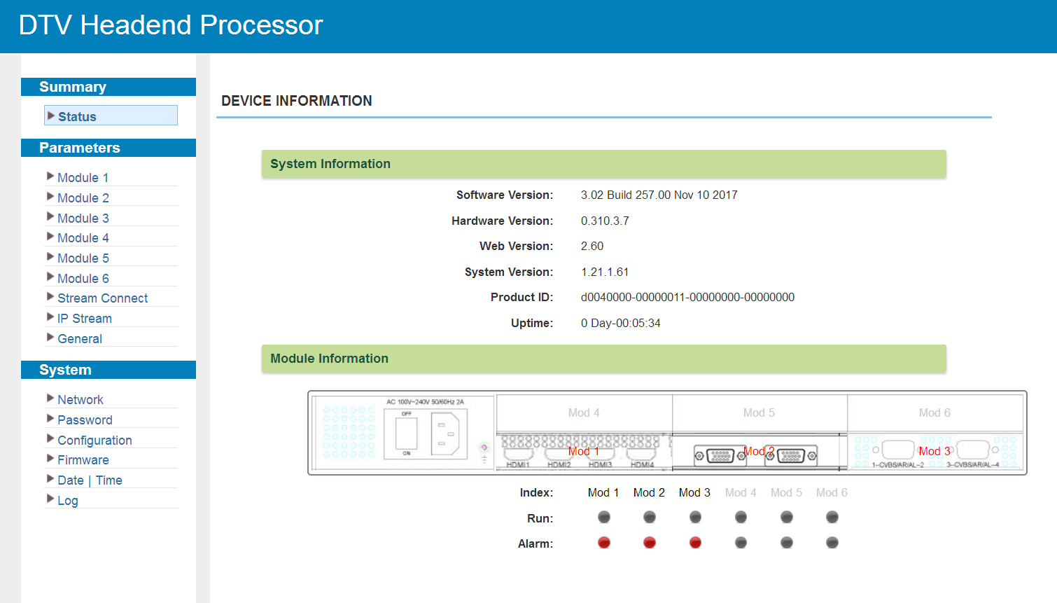
A green Run indicator means the transport stream of the module is normal; a red Alarm indicator means the module reports a fault.
Common Controls
Several screens are shared by all modules that multiplex programs. They are described here once and referenced from the module sections below.
Multiplexing Screen
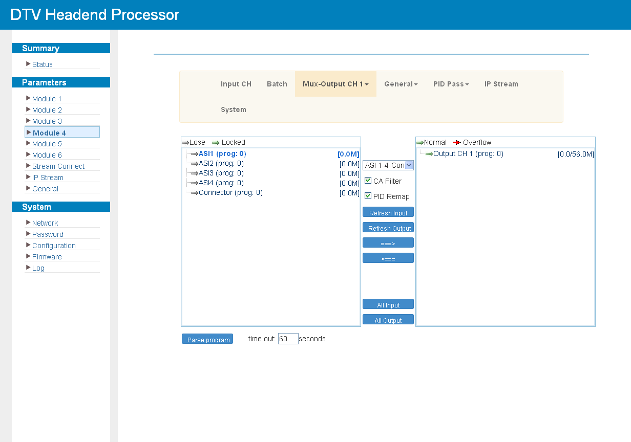
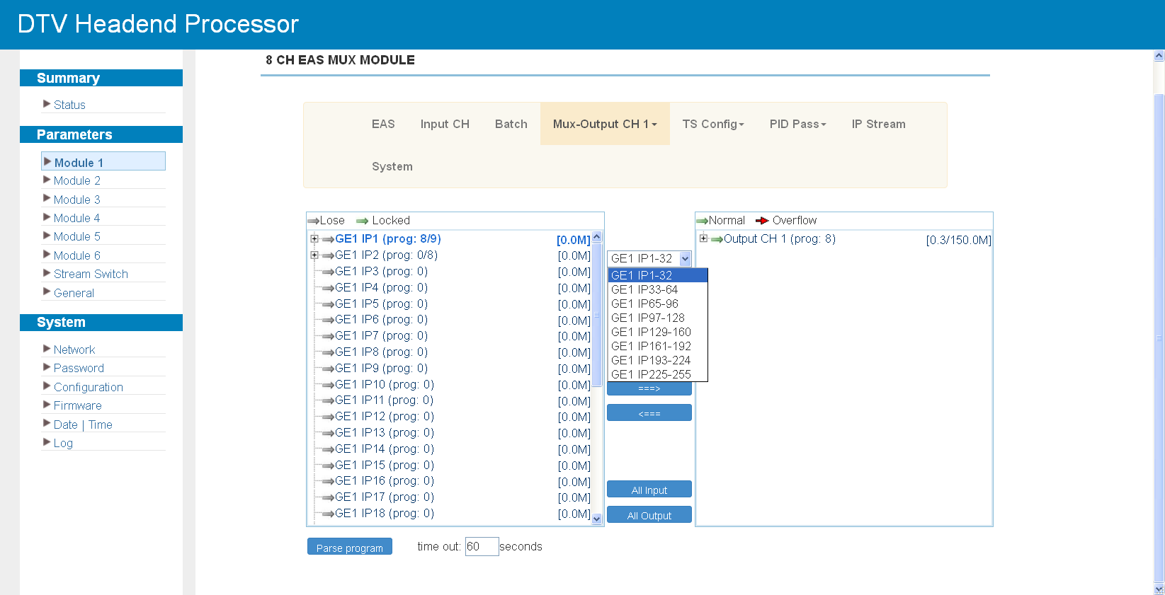
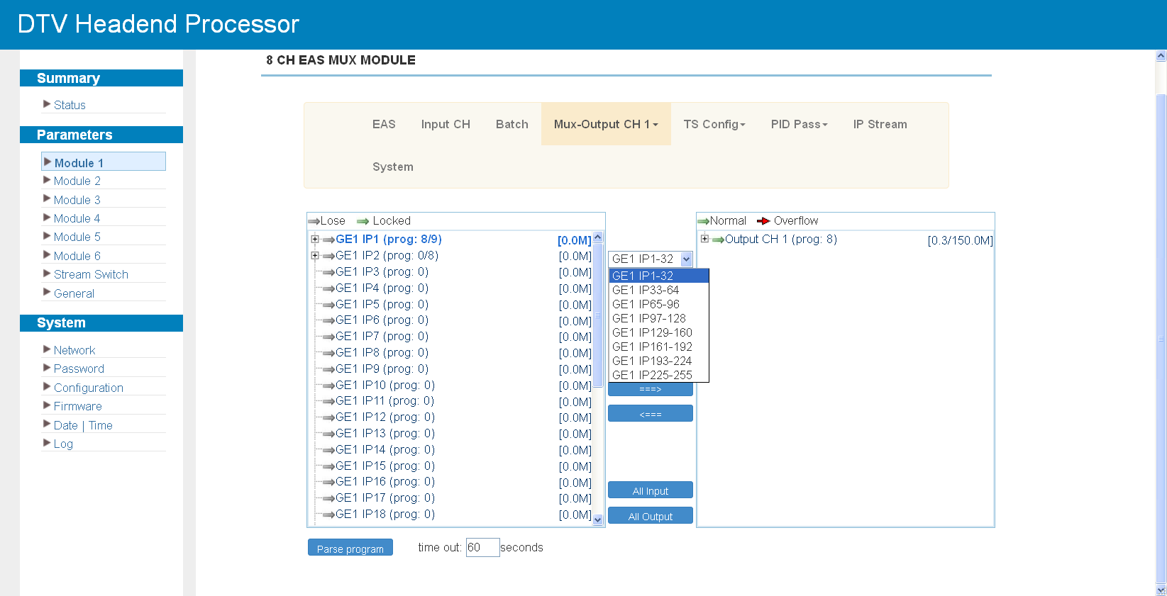
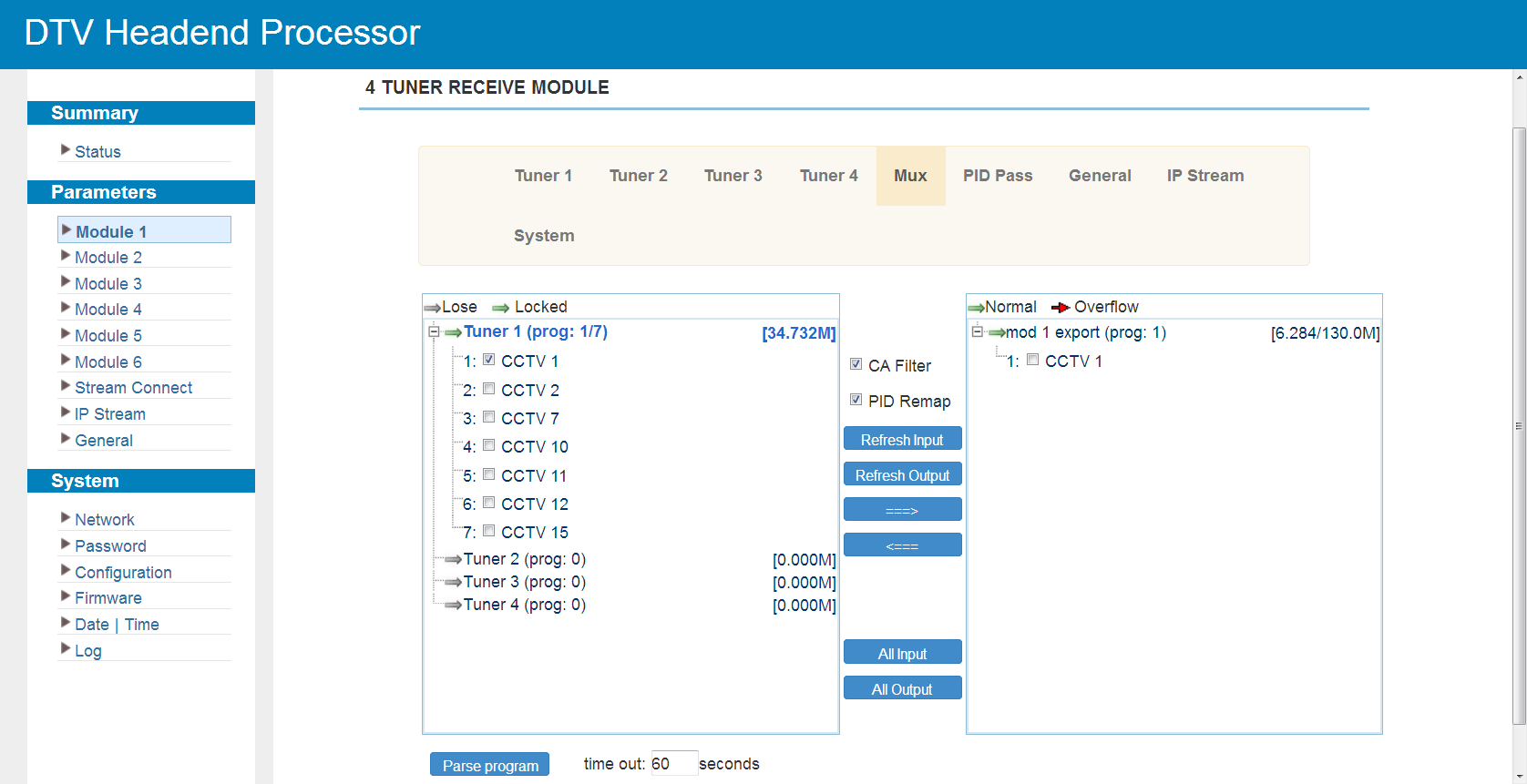
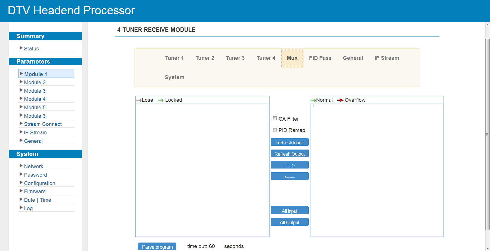
The "Mux" screen is split into three areas: the input area on the left, the operation area in the middle and the output area on the right. Programs are selected in the input area and transferred to the output area, which represents the transport stream leaving the module.
In the input list, "Module export" means the stream is passed to the chassis main board, and "Connector" means the stream comes back from the main board after processing.
The operation area provides the following controls:
-
"CA Filter" — enables or disables filtering of conditional-access packets.
-
"PID Remap" — enables or disables PID remapping.
-
Refresh Input and Refresh Output — reload the input and output program information.
-
=⇒ — transfer the selected input programs to the output; ⇐= — remove programs from the output.
-
All Input and All Output — select all programs in the corresponding list.
-
Parse program — parse the input programs; the adjacent field sets the parsing time limit in seconds.
Program Modification
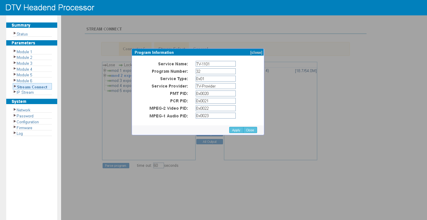
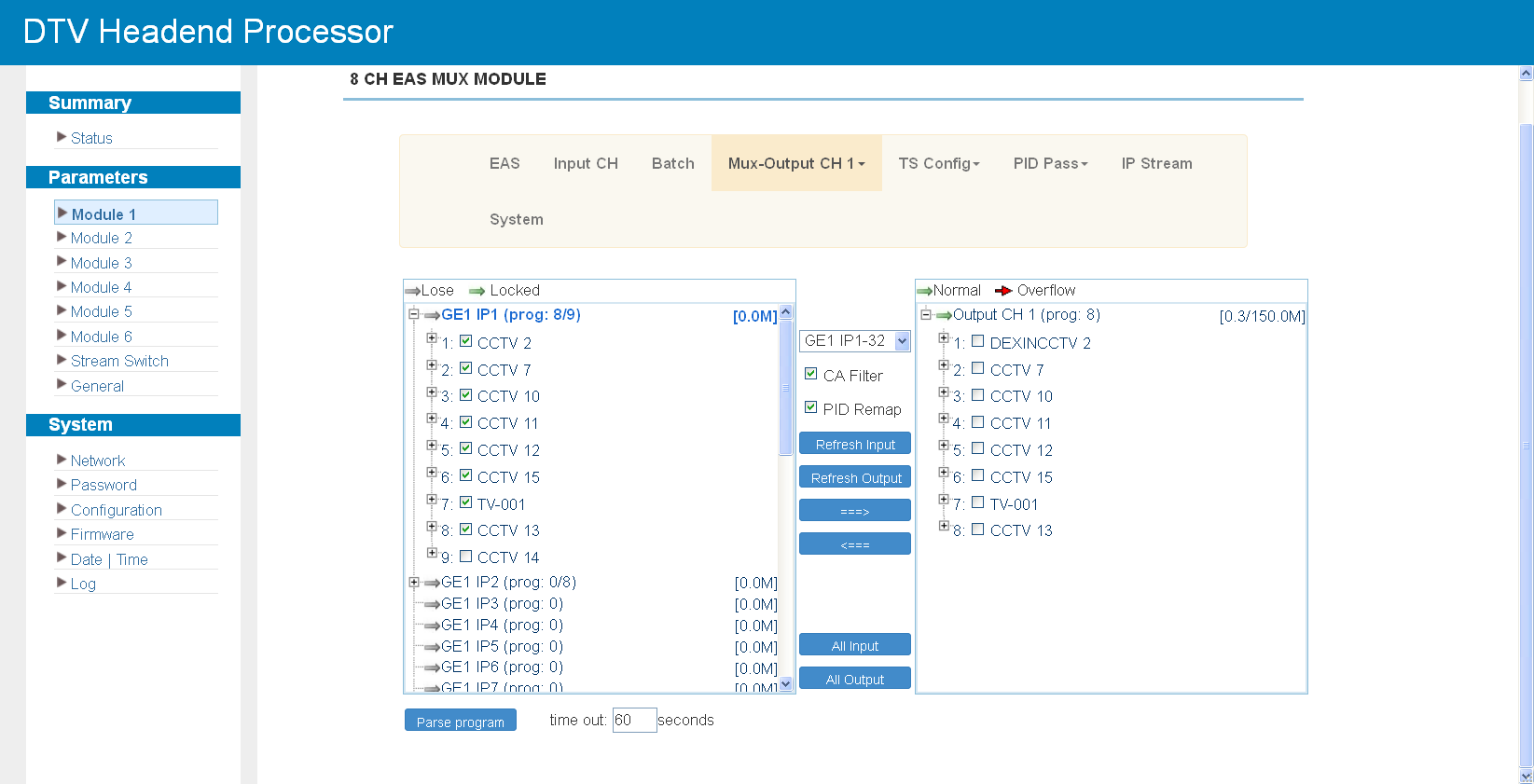
Clicking a program in the output area opens a dialog box where the program information can be edited: service name and provider, program number, logical channel number, PMT, PCR, video and audio PIDs. Enter the new values and click Save to apply them.
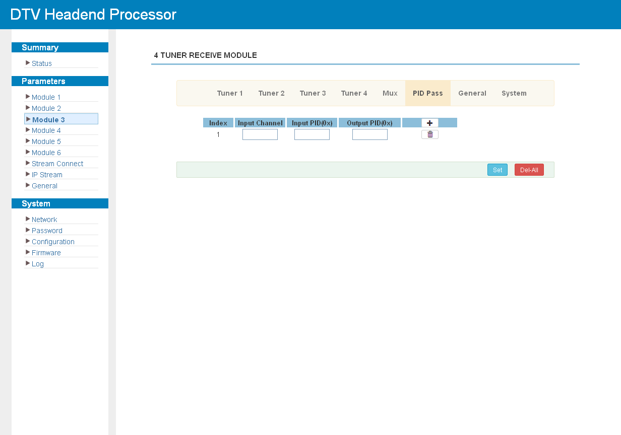
PID Pass
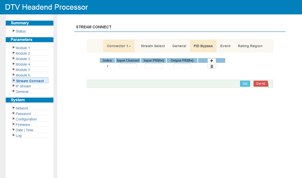
The "PID Pass" screen lists the PIDs that are passed through the module untouched, bypassing the multiplexer. Click the add button to create more rows, enter the PID values and apply the changes.
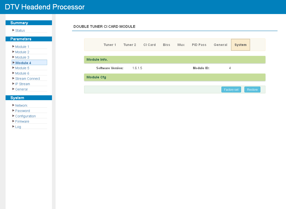
Module System Page
The "System" screen of a module shows its software and hardware versions and provides the module-level maintenance commands. Firmware files and update instructions are provided by NetUP technical support on request.
Multiplexing Modules
M-MUX-4ASI
The module has four bi-directional ASI ports and two GE ports, each supporting 256 IP inputs.
Click "Input CH" to set the input parameters:
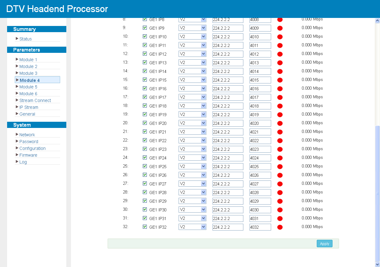
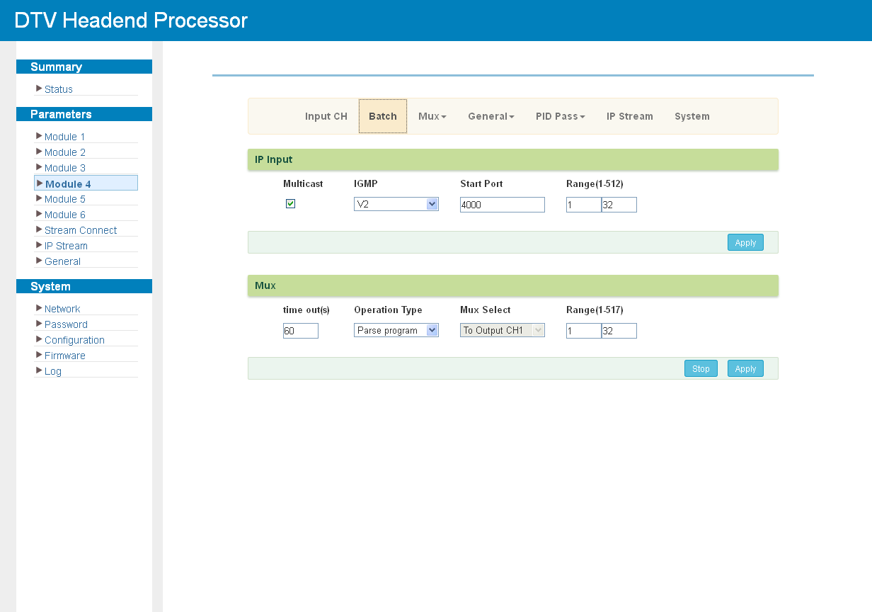
Click "Batch" to set the IP input and general multiplexing parameters for the whole module at once:
Click "Mux" to select the programs for the output transport stream. The controls of this screen are described in Multiplexing Screen.
Clicking a program in the output area opens the editing dialog (see Program Modification):
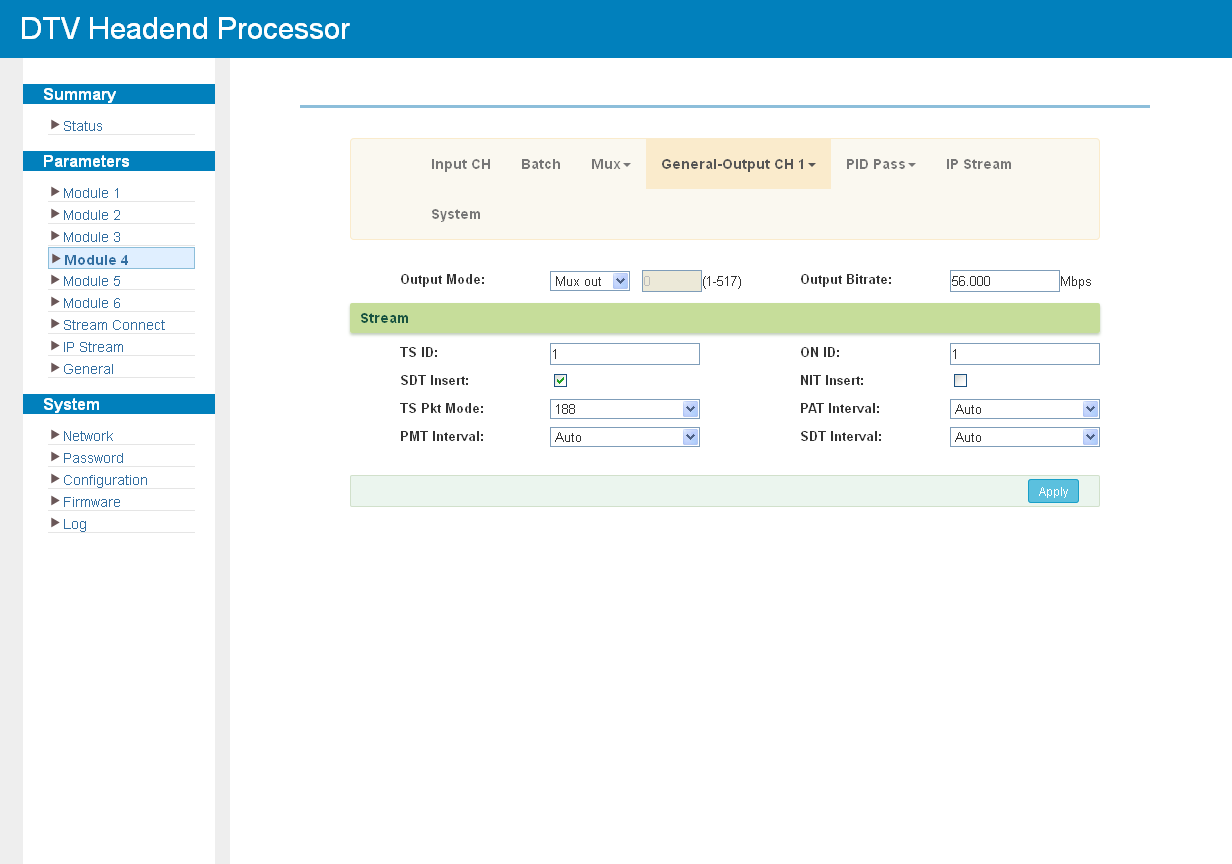
Click "General" to set the parameters of each output stream:
Click "PID Pass" to add the PIDs that must pass through (see PID Pass):
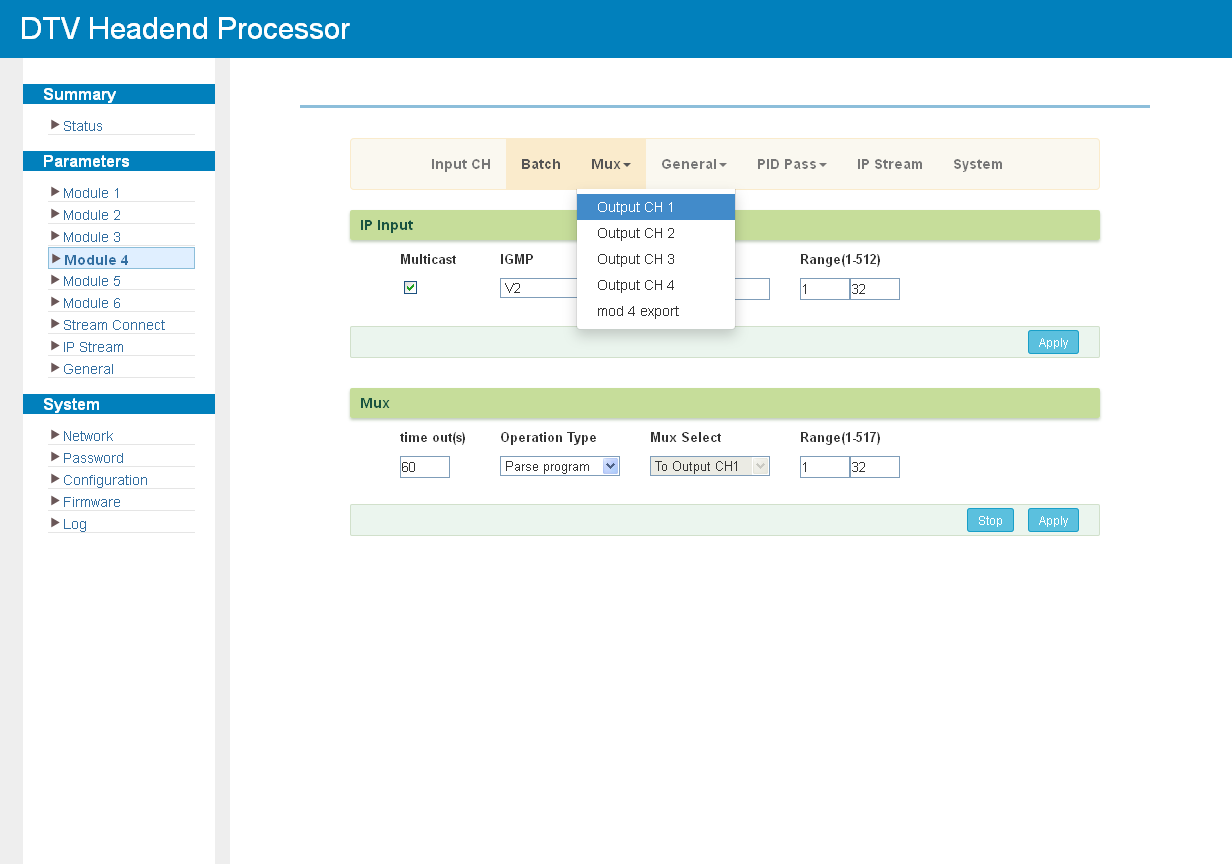
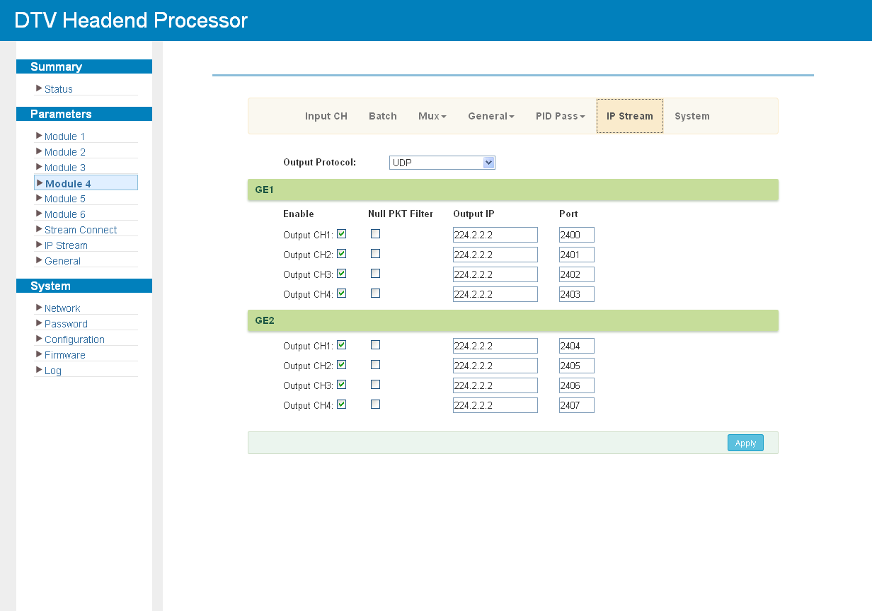
The module outputs four transport streams through the two GE ports; each channel on GE1 and GE2 has its own IP address and port. Click "IP Stream" to set the output parameters:
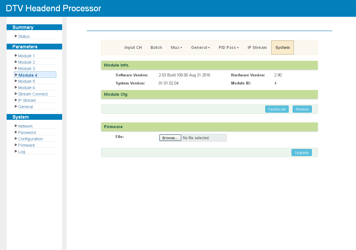
Click "System" to check the module information (see Module System Page):
M-MUX-EAS4 and M-MUX-EAS8
The module supports one ASI input as the emergency alert source and 256 IP inputs through the GE1 port. M-MUX-EAS4 provides four IP outputs with up to 16 programs each; M-MUX-EAS8 provides eight IP outputs with up to 8 programs each.
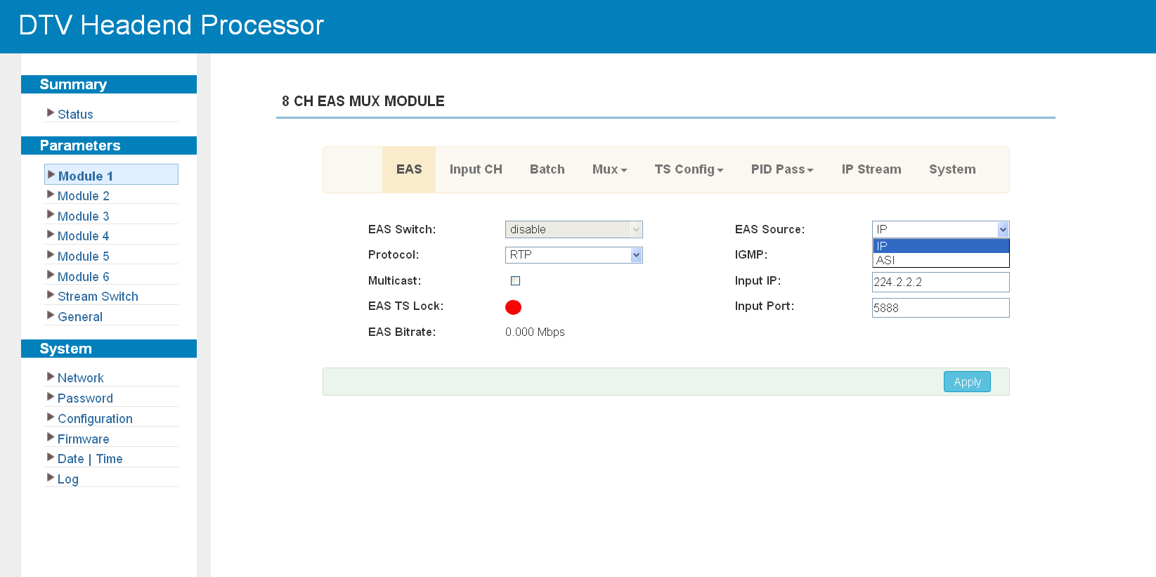
Click "EAS" to set the alert parameters. The alert source can be the ASI input or the 256th IP input; both must be SPTS and cannot be multiplexed.
Click "Input CH" to set the input parameters; IP input is received over UDP or RTP:
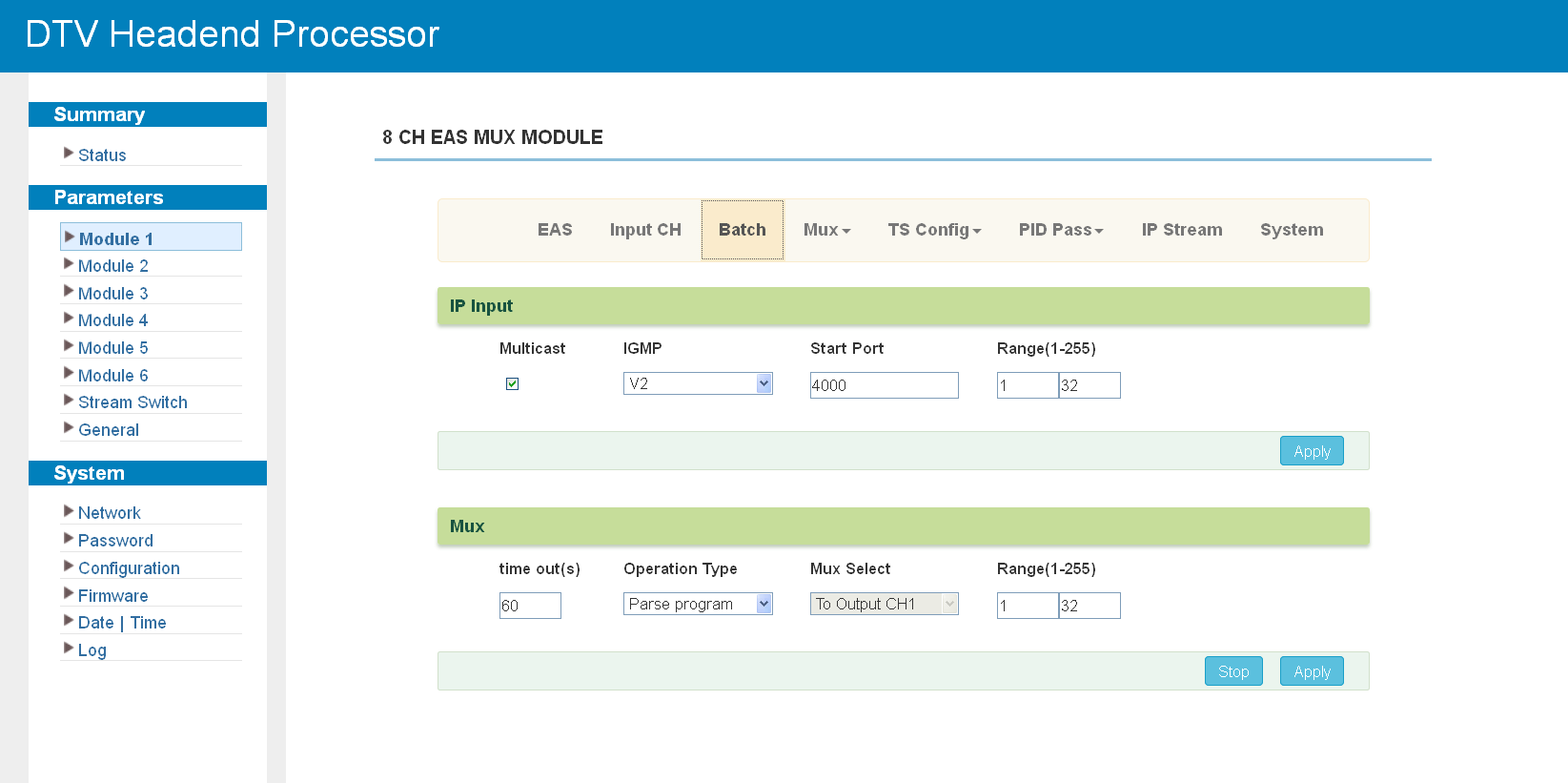
Click "Batch" to set the IP input and general multiplexing parameters for the whole module:
Click "Mux" to select the programs for the output (see Multiplexing Screen):
Program editing works as described in Program Modification:
The "General", "PID Pass", "IP Stream" and "System" screens follow the same pattern as the other multiplexing modules:
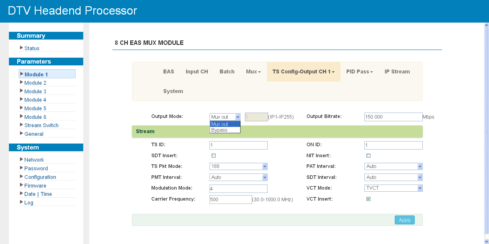
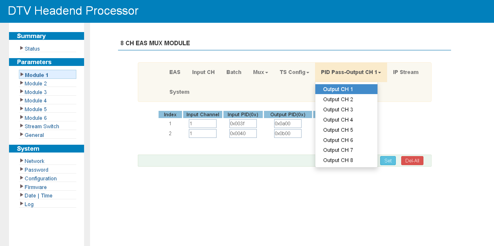
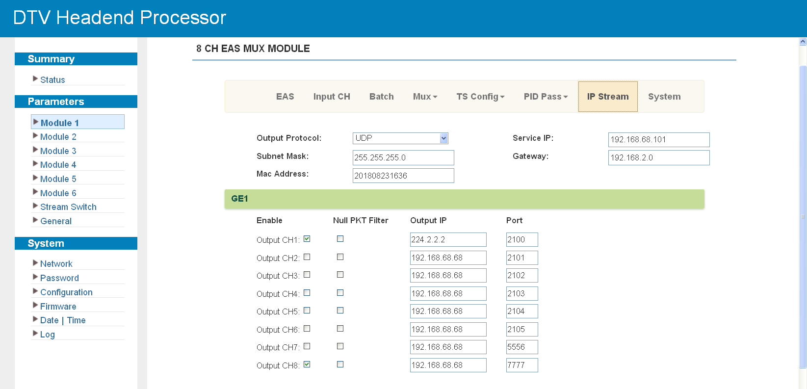
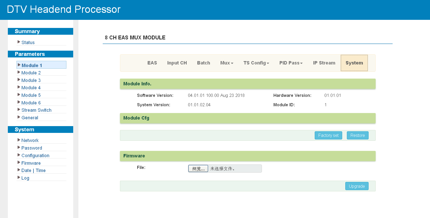
M-MUX-5ASI
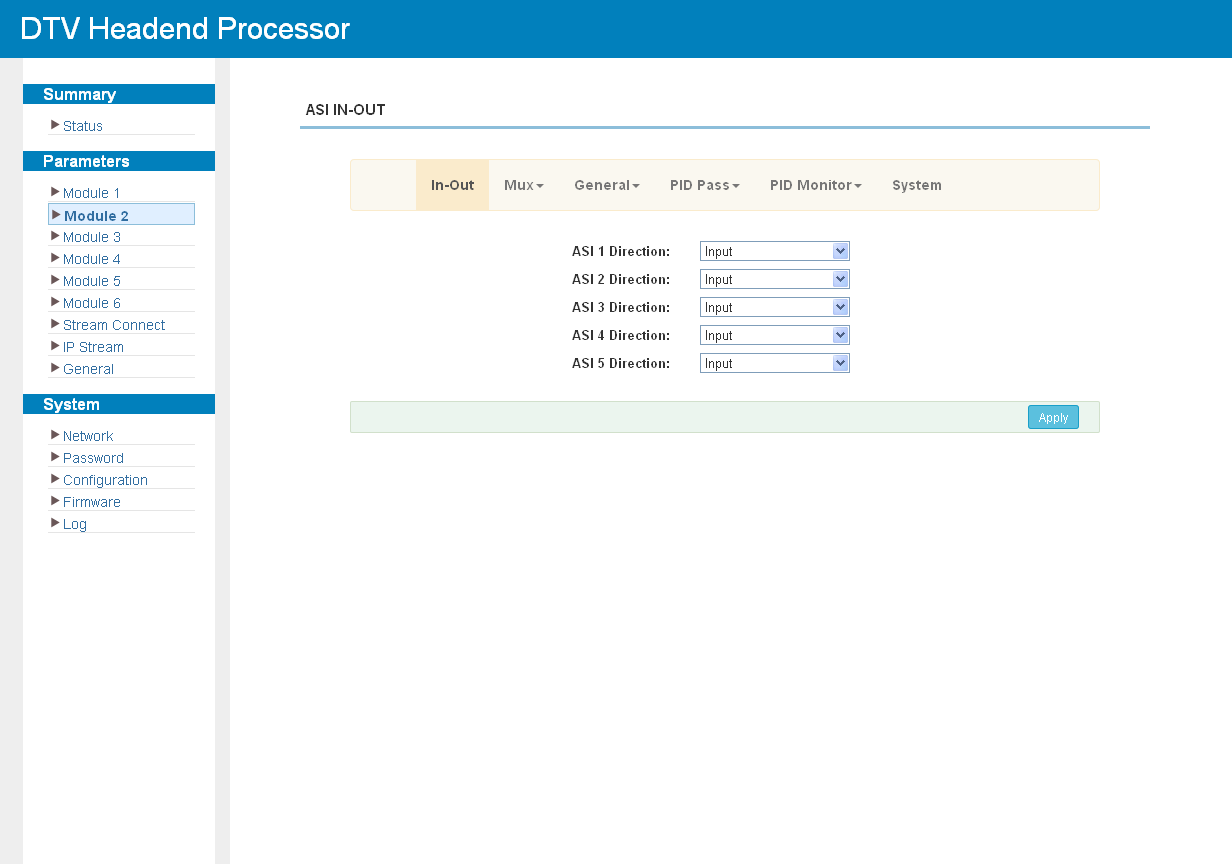
The module has five bi-directional ASI ports. Click "In-Out" to set the direction of each port:
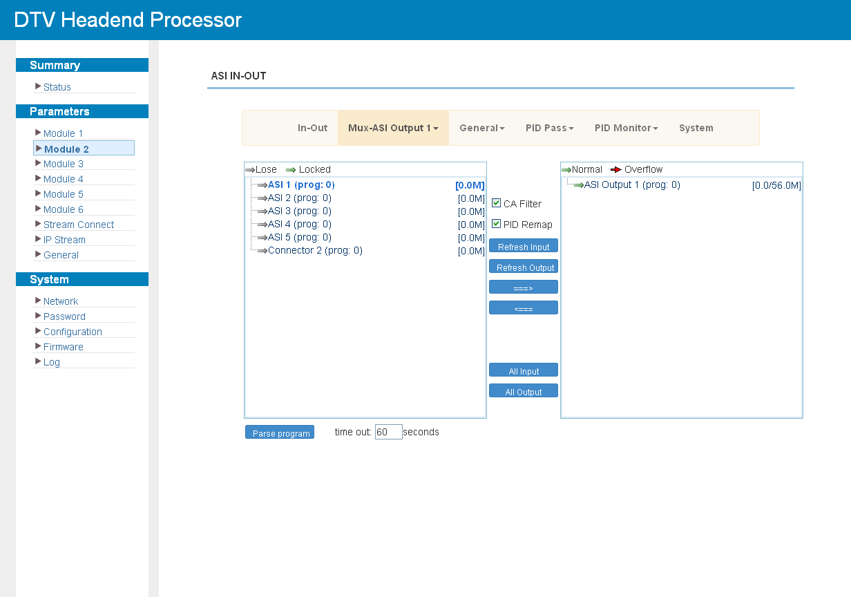
Click "Mux" to select the programs for the output. The output channel is chosen from six options: ASI 1 to ASI 5 and the module export to the chassis.
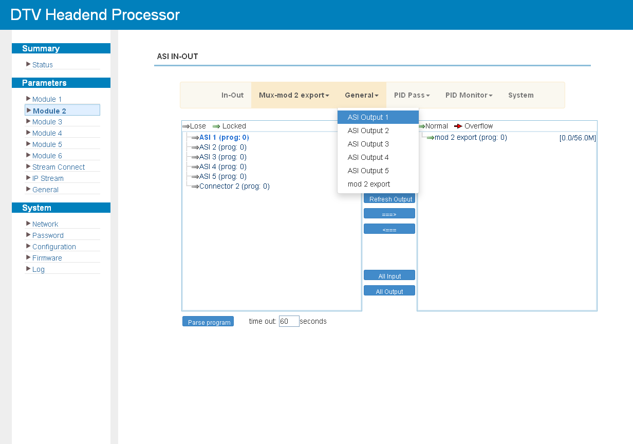
Click "General" to set the parameters of each output stream:
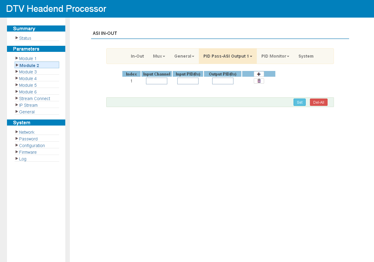
Click "PID Pass" to add the PIDs that must pass through:
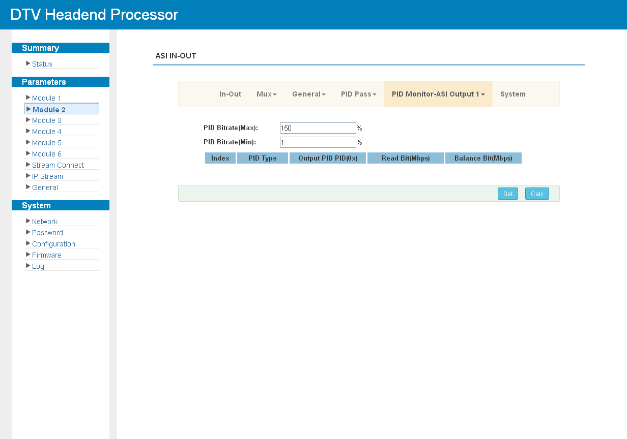
Click "PID Monitor" to review the PIDs present in the streams:
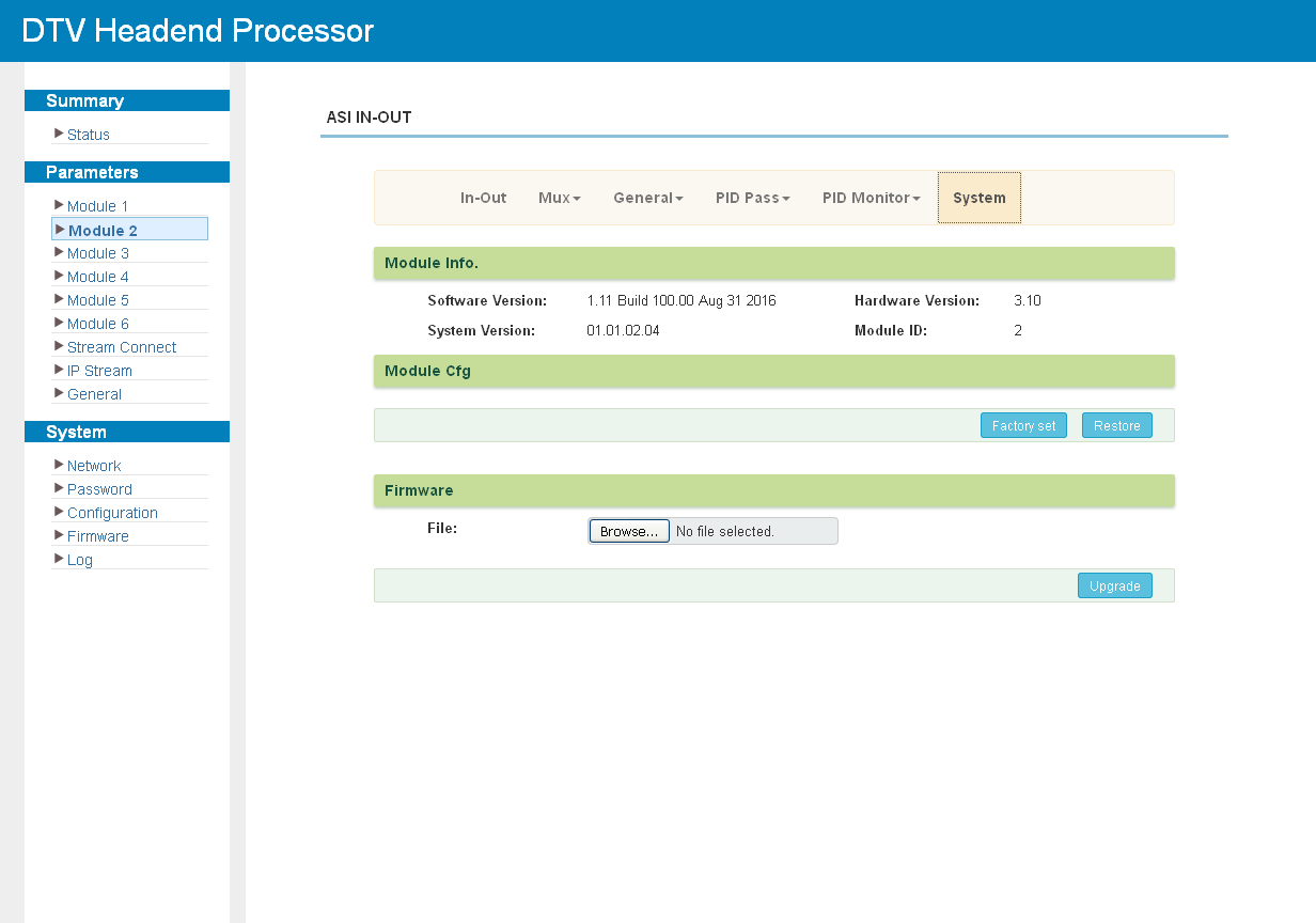
Click "System" to check the module information:
Encoding Modules
M-ENC-4CVBS
Click "Encoding CH1-CH4" to set the encoding parameters of each channel. The screen shows the video and audio settings together with the status of each channel.
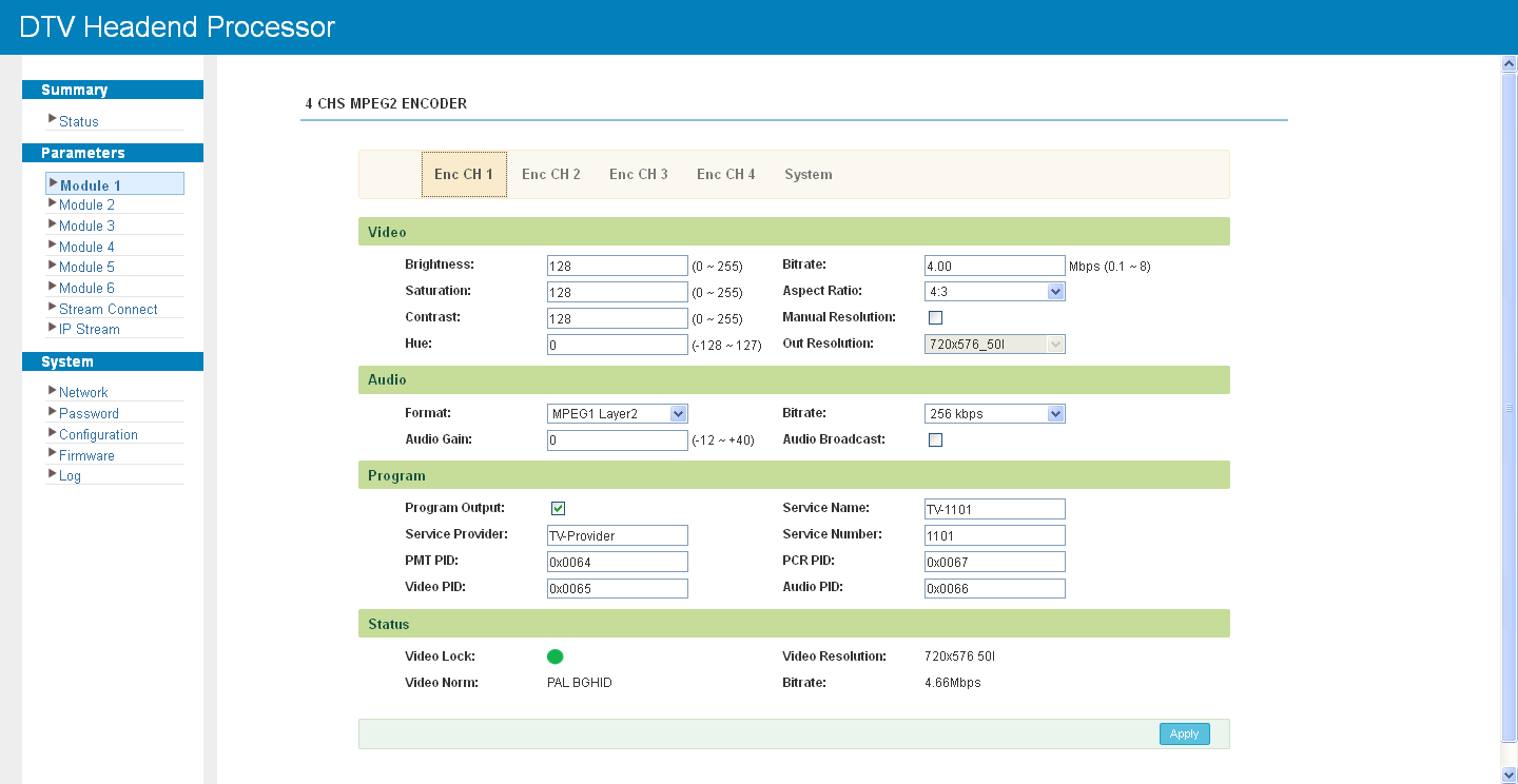
Click Apply to apply the modified parameters.
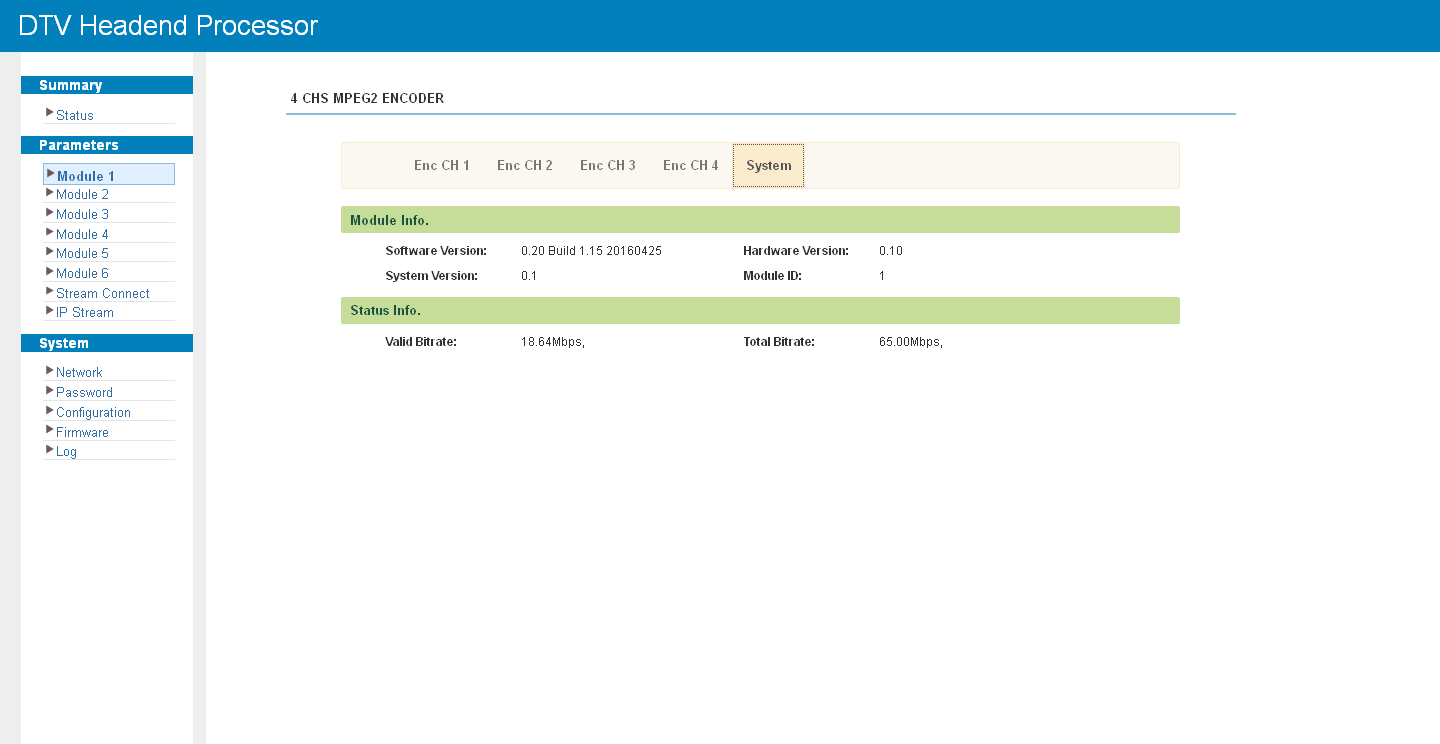
Click "System" to check the module information:
M-ENC-8CVBS
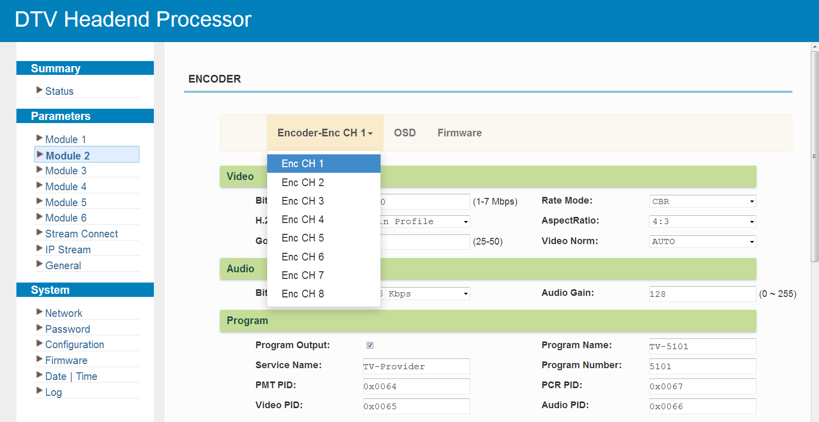
Click "Enc CH 1" to "Enc CH 8" to set the parameters of each encoding channel. A green video lock indicator means a source signal is present at the input.
Click "OSD" to overlay a logo, a caption or a QR code. The overlay can be set for one encoding channel or applied to all channels at once. A separate tab is used for each overlay type: a logo is uploaded as an image file, a caption is entered as text with the required font, text colour and background colour, and a QR code is either uploaded as an image or generated from a URL.
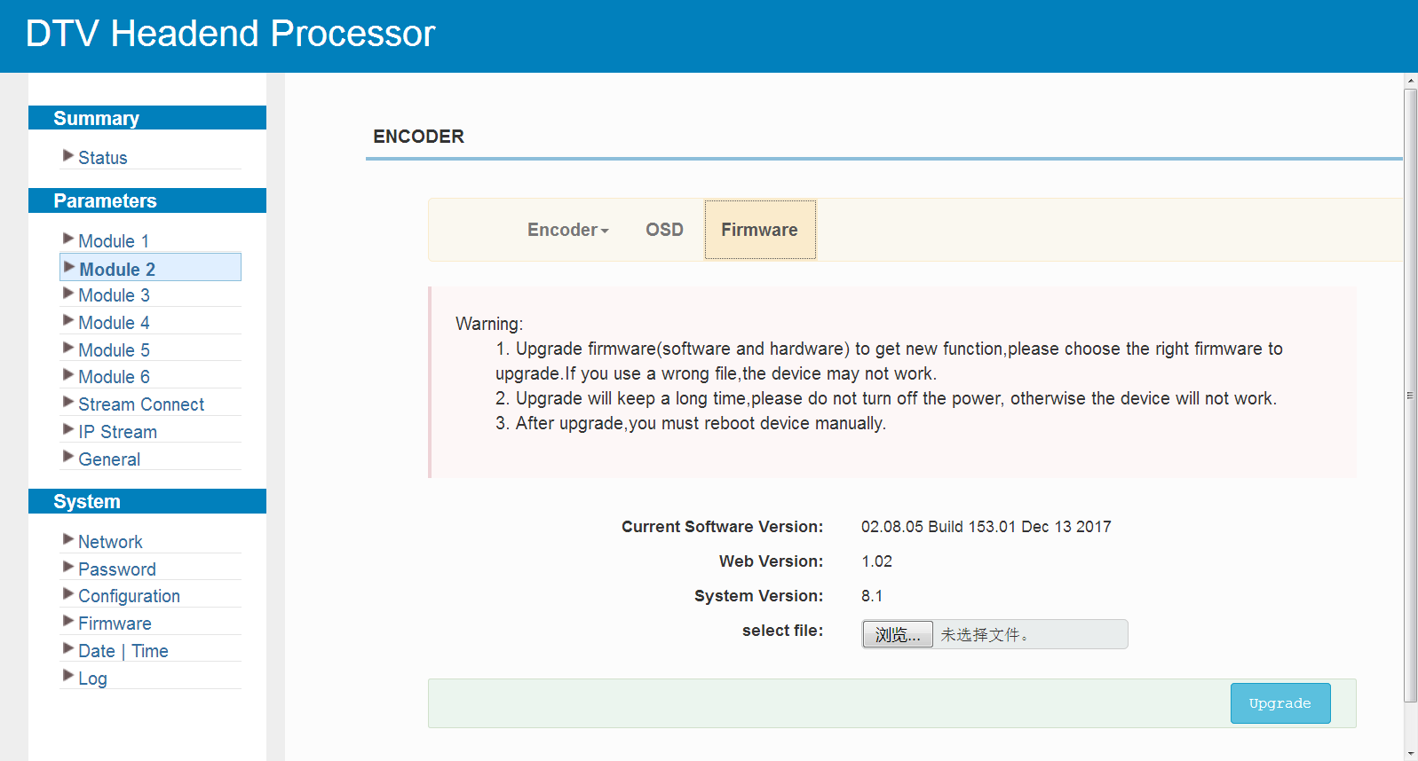
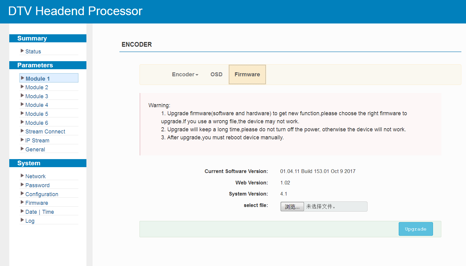
Click "Firmware" to check the current software, web and system versions and to upgrade the module:
M-ENC-4AV
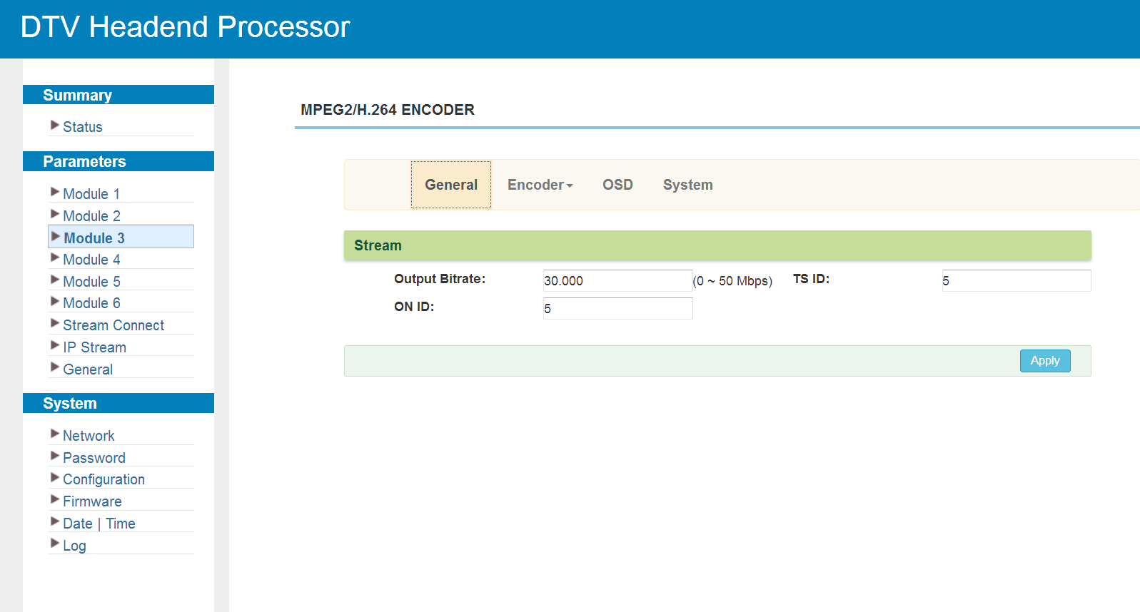
Click "General" to check the stream parameters:
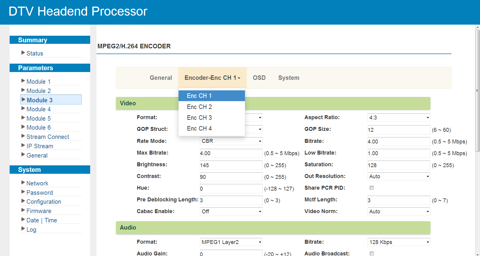
Click "Enc CH1" to "Enc CH4" to set the encoding parameters. A green video lock indicator means a source signal is present at the input.
Click "OSD" to set the logo, caption and QR code parameters. The overlay is positioned by dragging it on the preview; right-clicking an overlay opens its parameters, and the "Date" tab sets the period during which the overlay is shown. Select "on" to display the overlay, and choose one channel or all channels to apply it to.
Click "System" to check the module information:
M-ENC-4HDMI
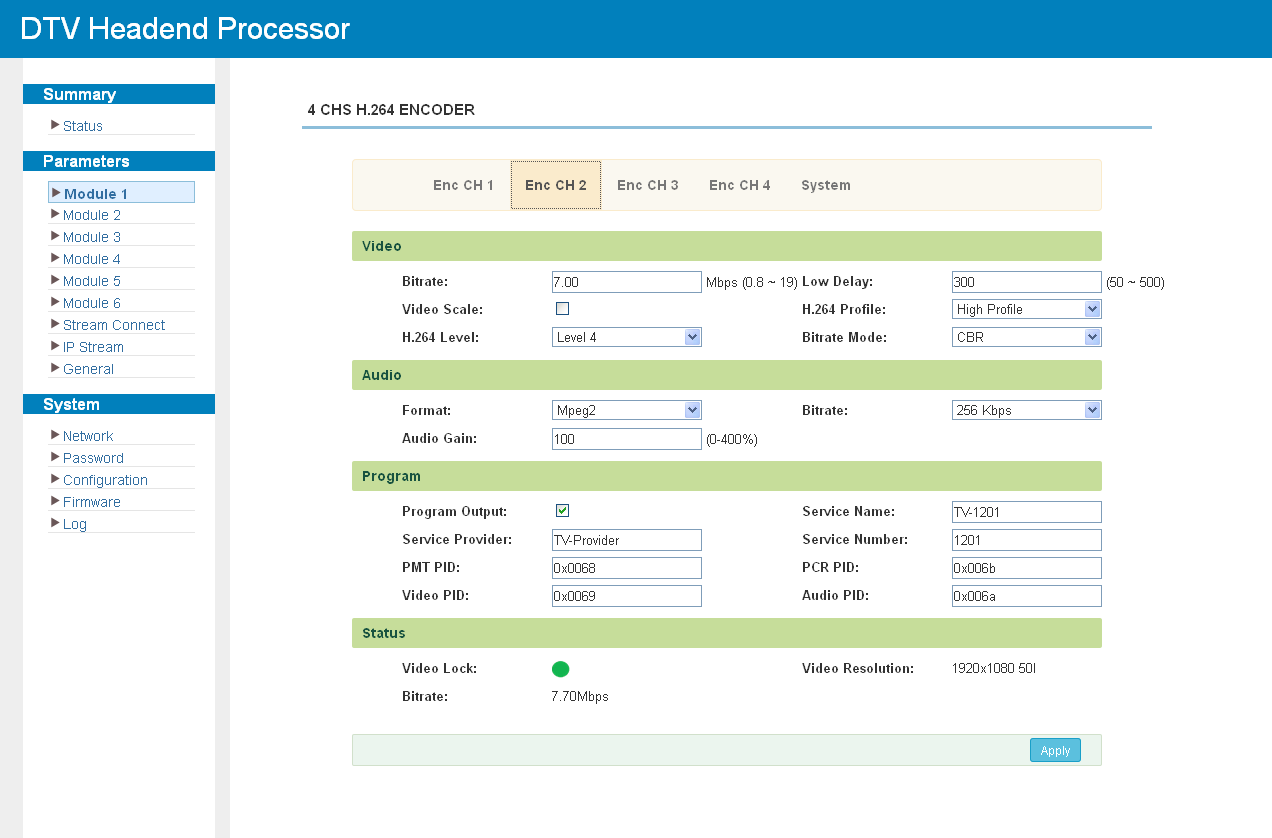
Click "Enc CH 1" to "Enc CH 4" to set the parameters of each encoding channel: video bit rate and scaling, H.264 profile and level, low delay, rate control mode, audio format and bit rate, and the program identification (service name and provider, PMT, PCR, video and audio PIDs). The status block shows the video lock, the input resolution and the current bit rate.
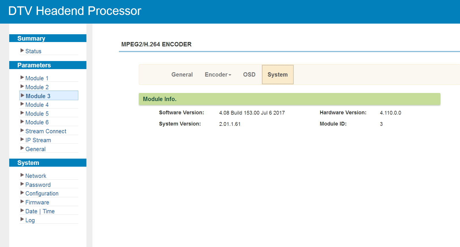
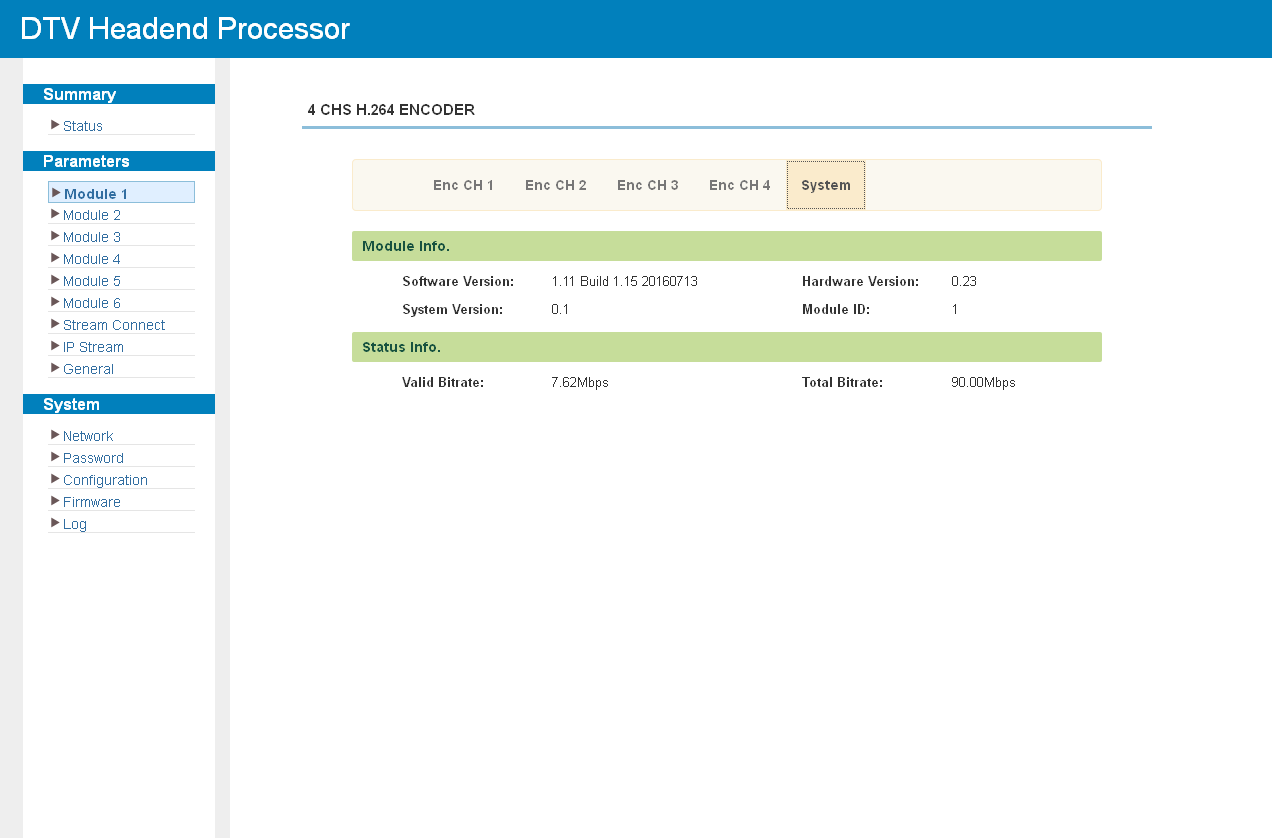
Click "System" to check the module information:
Some versions of the module support overlays. On those, the encoding channel screen carries an additional "OSD" tab:
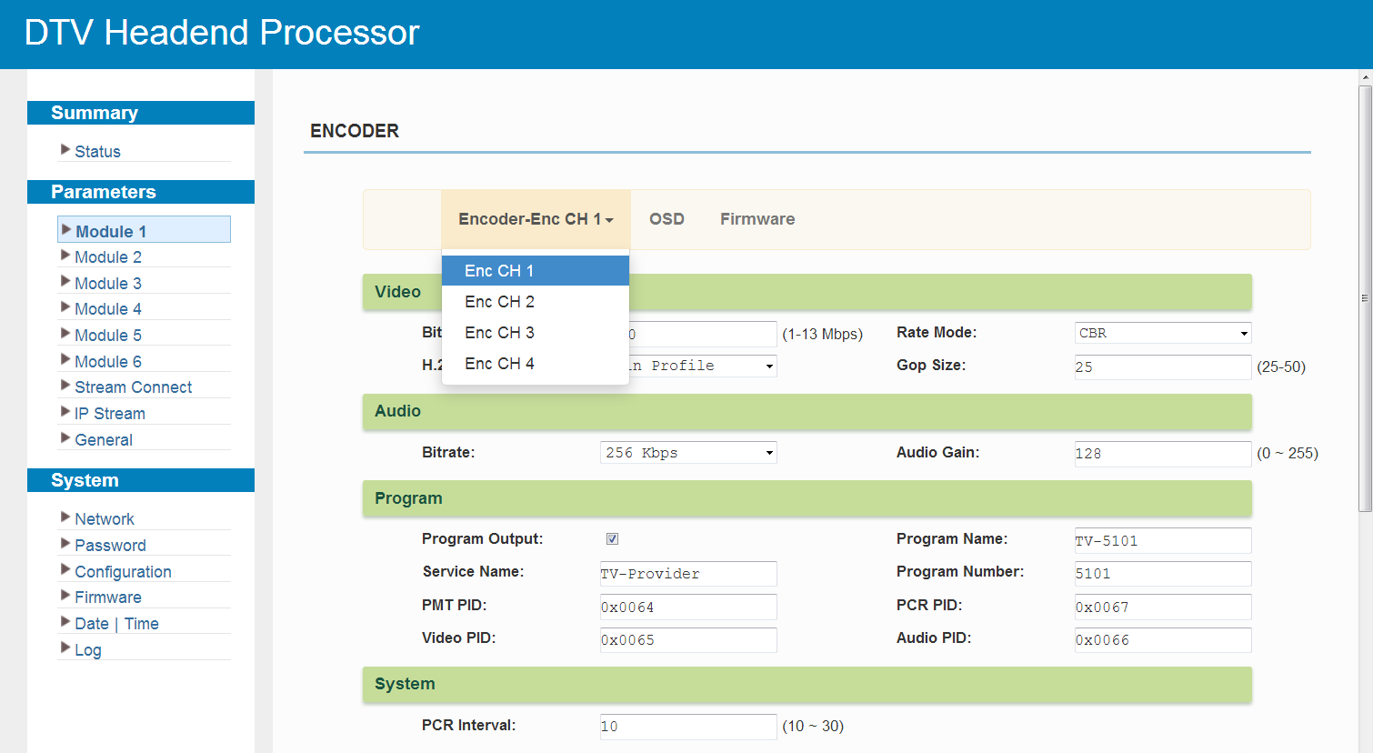
The "OSD" tab adds a logo, a caption or a QR code to one encoding channel or to all channels at once.
Click "Firmware" to check the current versions and upgrade the module:
M-ENC-4UHD
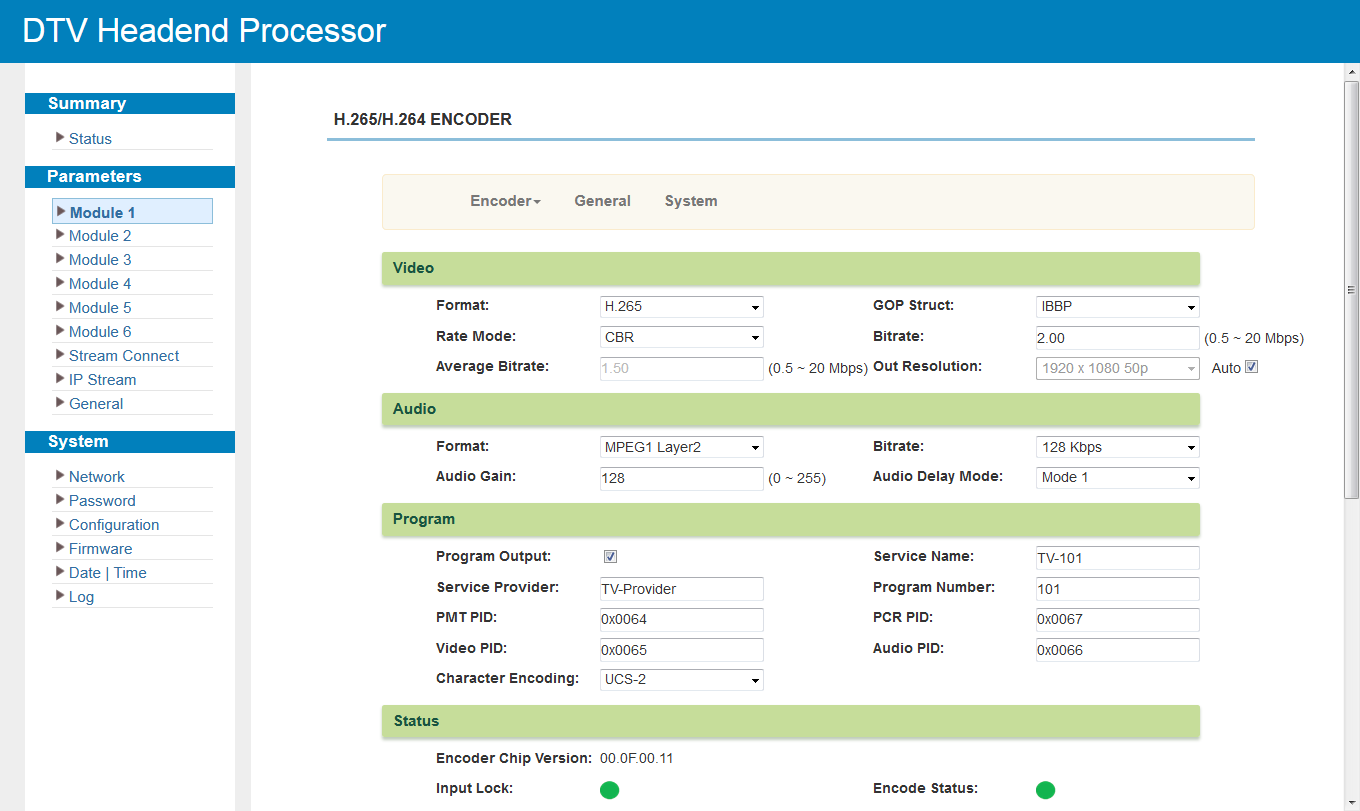
Click "Encoder" to display the programs of each encoding channel and to set the video and audio parameters.
|
|
Only channels 3 and 4 encode 3840×2160_30P and 3840×2160_29.97P with HEVC/H.265. |
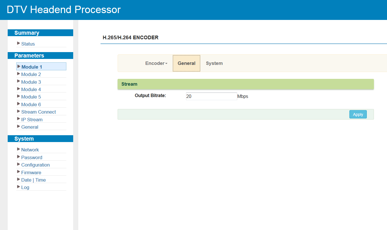
Click "General" to set the output bit rate:
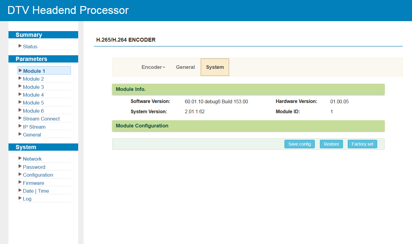
Click "System" to check the module information:
M-ENC-2HDMI
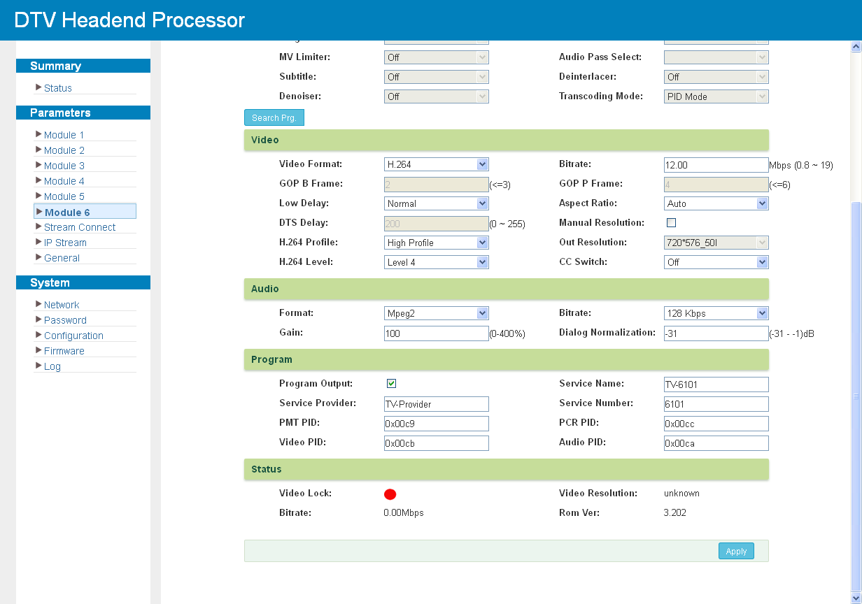
The module can work as an encoder or as a transcoder. Click "Encoder/Transcoder 1" or "Encoder/Transcoder 2" to set the parameters of the corresponding channel:
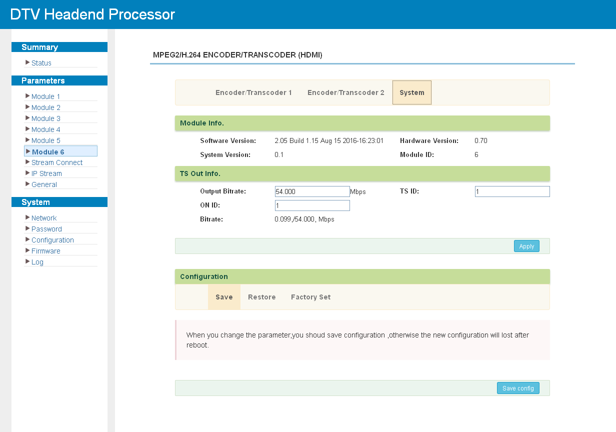
Click "System" to check the module information:
M-ENC-2SDI
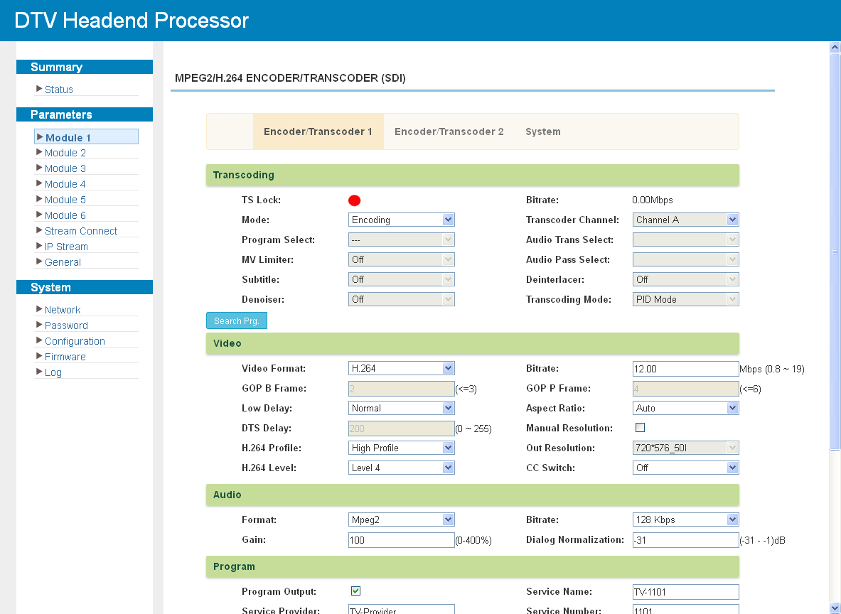
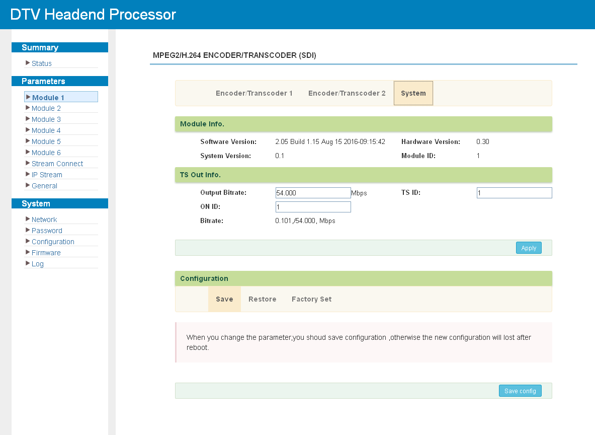
The module works in the same way as M-ENC-2HDMI, with SDI inputs instead of HDMI.
Tuner and Descrambling Modules
M-2S2CI
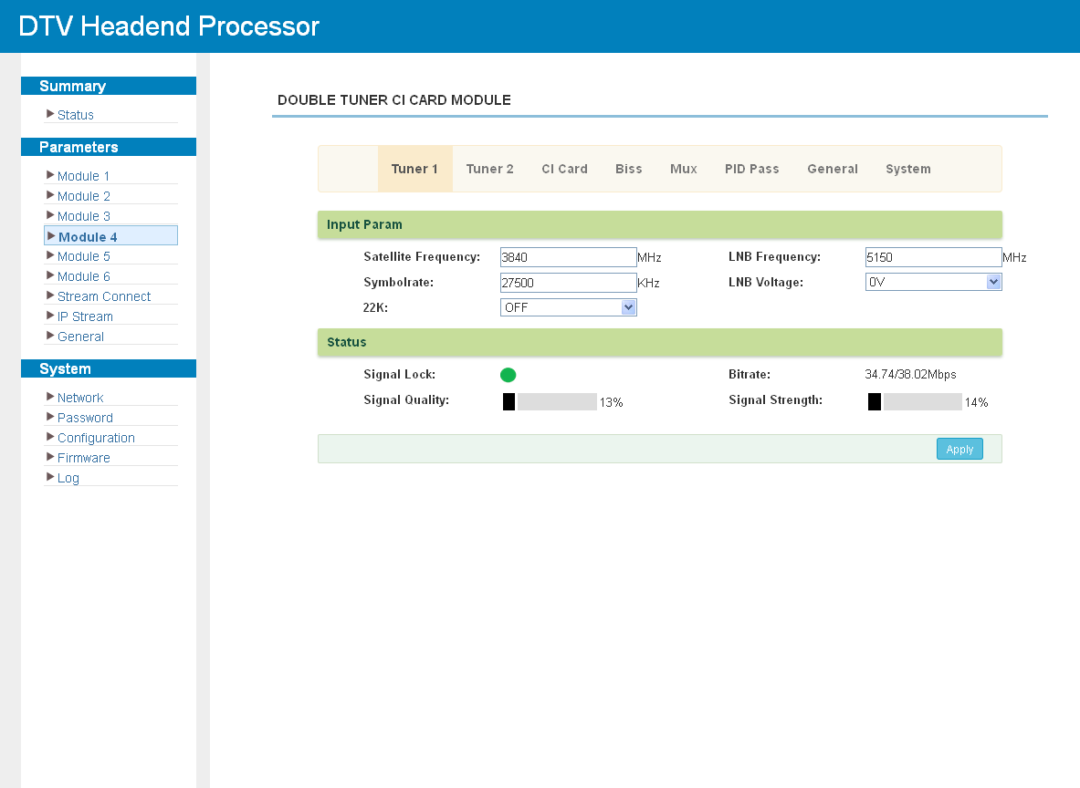
Click "Tuner1-2" to configure the tuner inputs. Enter the parameters of the source signal and click Apply to lock the tuners.
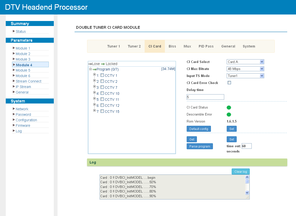
The module carries two CI slots for descrambling programs from the tuner inputs. Click "CI Card" to configure each card. One card can descramble programs from both tuner inputs; "Skip CI card" bypasses the card for free-to-air streams. The card error check can be enabled with the corresponding check box.
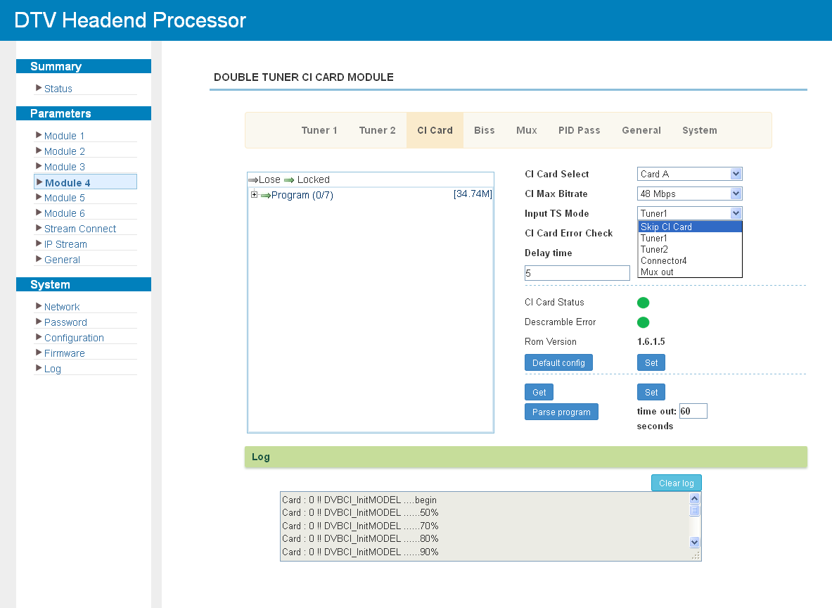
After configuring the card parameters, apply them and select the source in "Input TS Mode". The programs found in the selected stream are listed in the "Descramble" box:
Select the programs to be descrambled and apply the change. The number of programs that can be descrambled simultaneously depends on the CAM module in use. The number before the slash shows how many programs are being descrambled, the number after the slash — the total number of programs in the selected stream. Clicking the "+" symbol expands the program details.
Click "BISS" to configure BISS descrambling for the input channels:
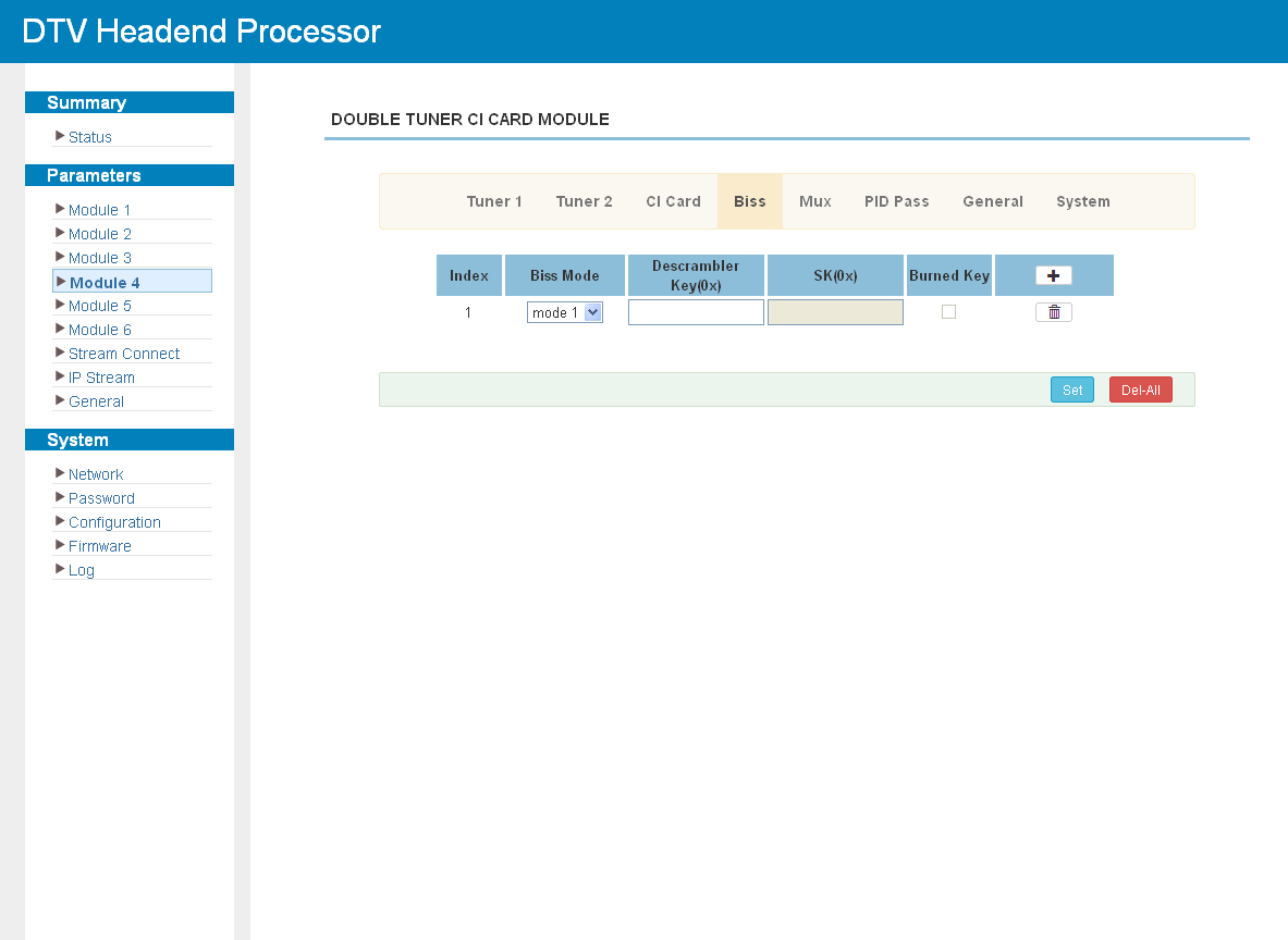
Click "Mux" to select the programs from the two tuners for the module output (see Multiplexing Screen):
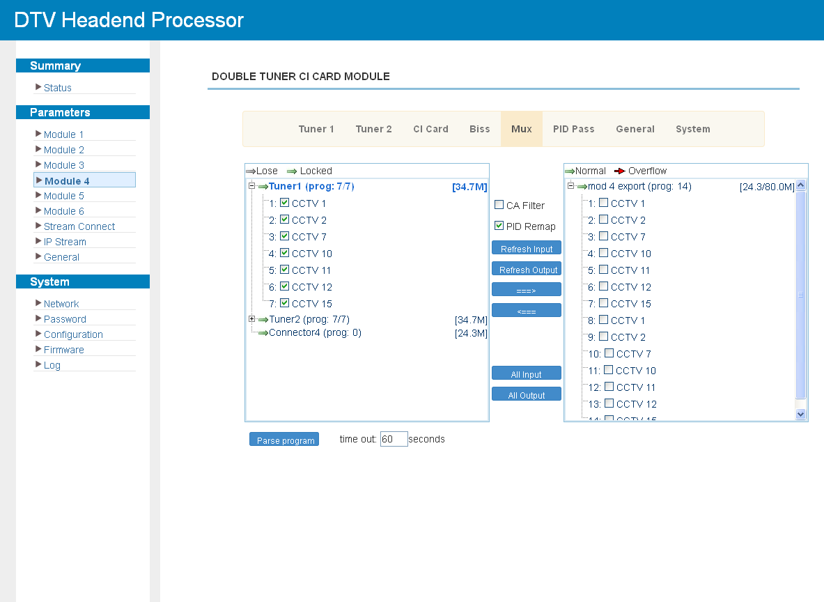
Program editing works as described in Program Modification:
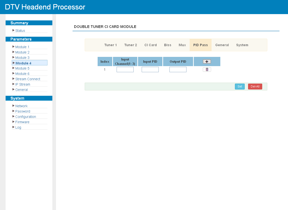
Click "PID Pass" to add the PIDs that must pass through:
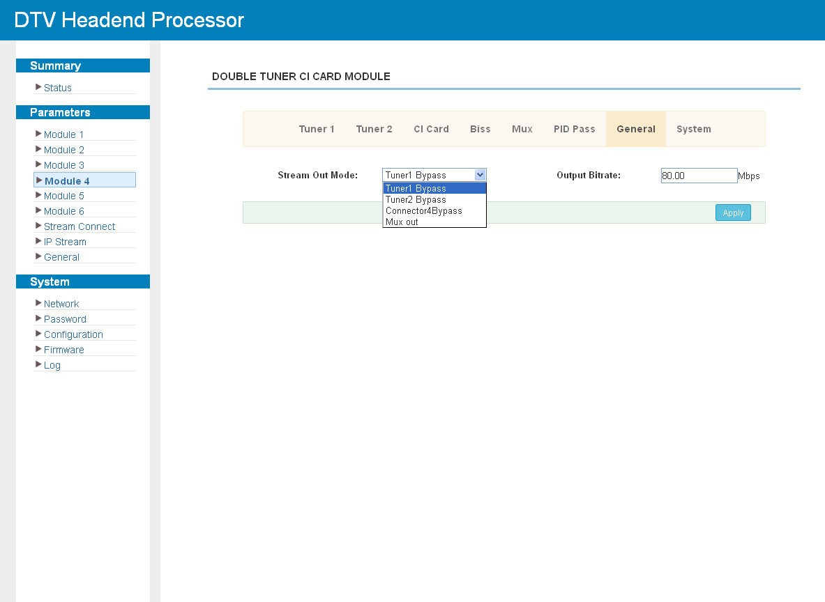
Click "General" to set the parameters of the output stream:
Click "System" to check the module information:
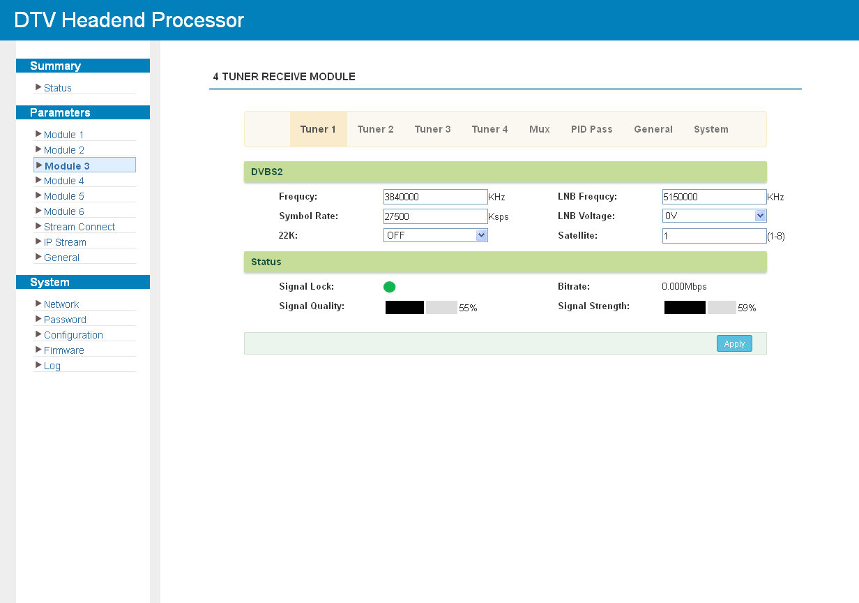
M-4S
Click "Tuner1-4" to set the RF parameters of the four tuner inputs:
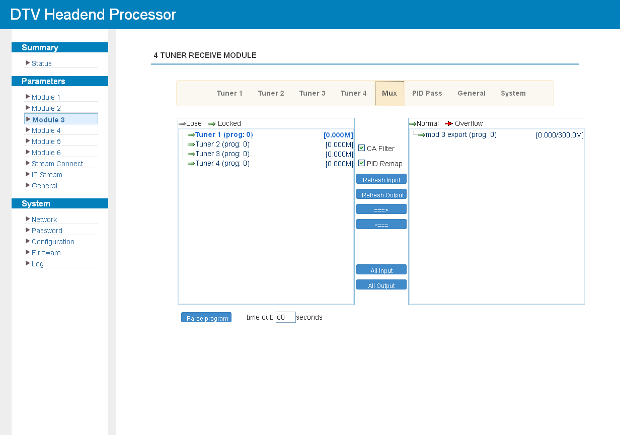
The module has no output ports of its own, so its streams are always passed to another module or to the chassis. Click "Mux" to select the programs from the four tuners (see Multiplexing Screen):
Click "PID Pass" to add the PIDs that must pass through:
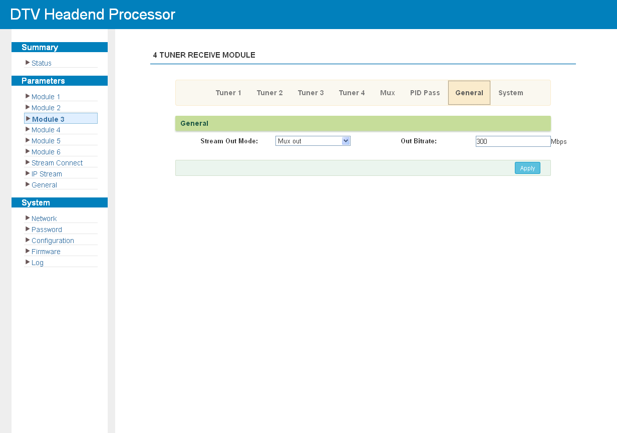
Click "General" to set the general parameters of the module:
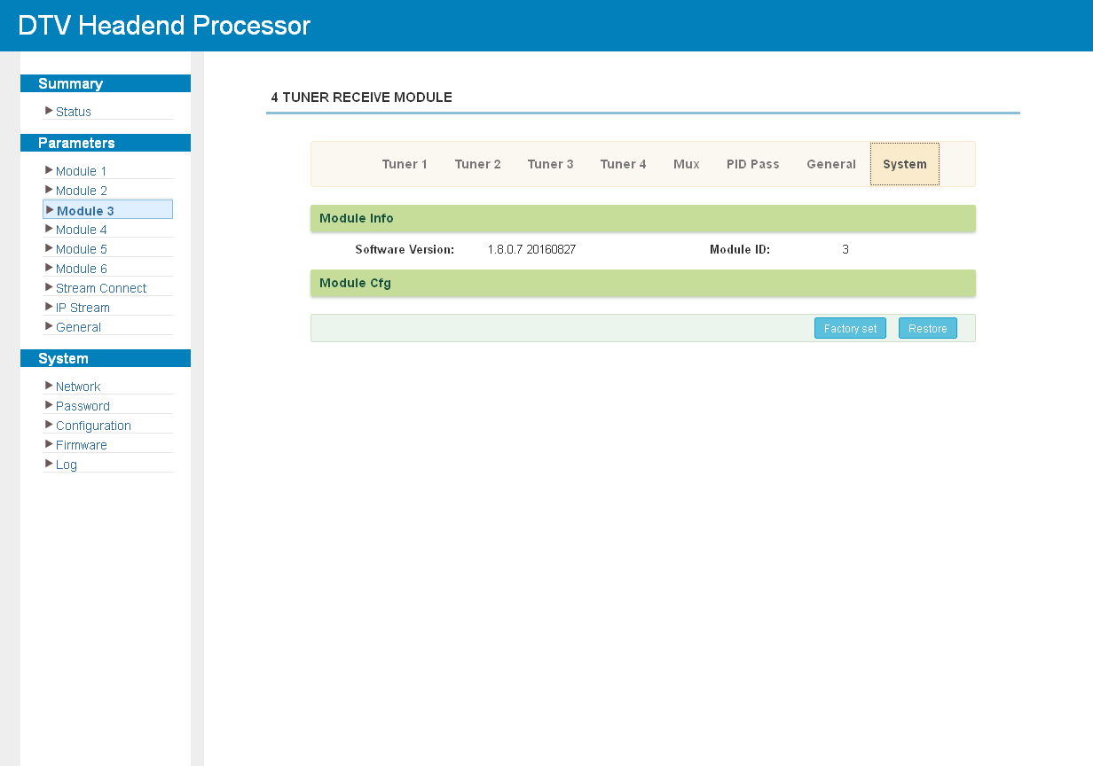
Click "System" to check the module information:
M-4TC
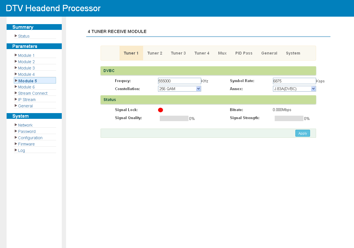
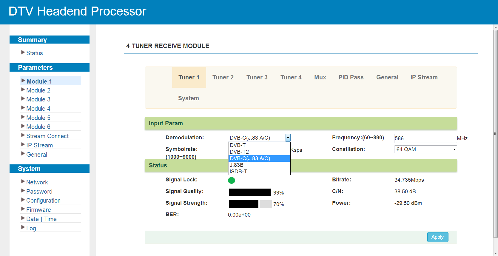
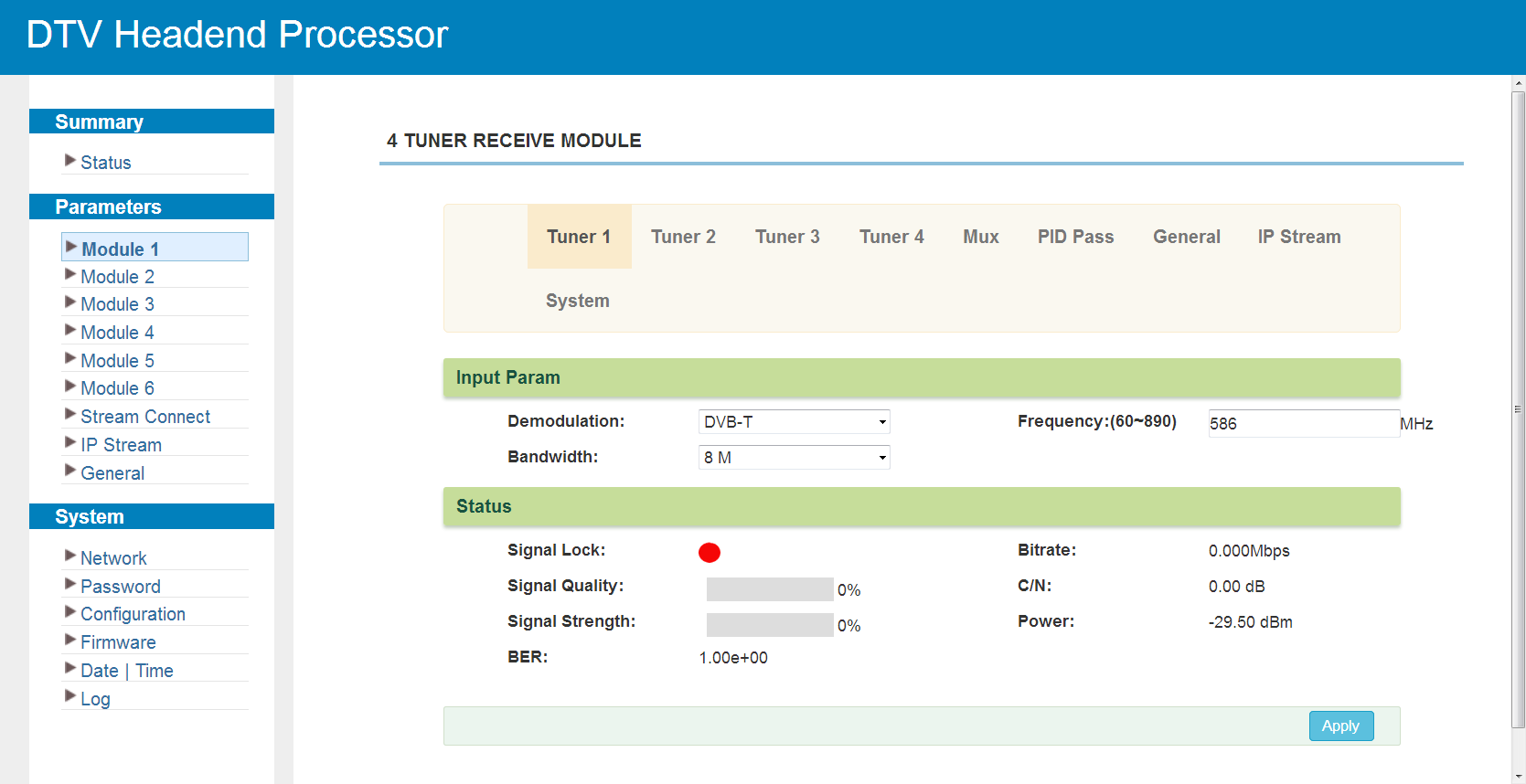
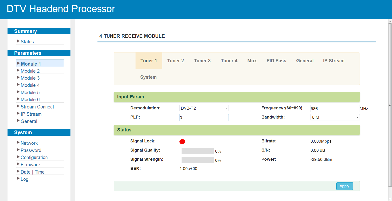
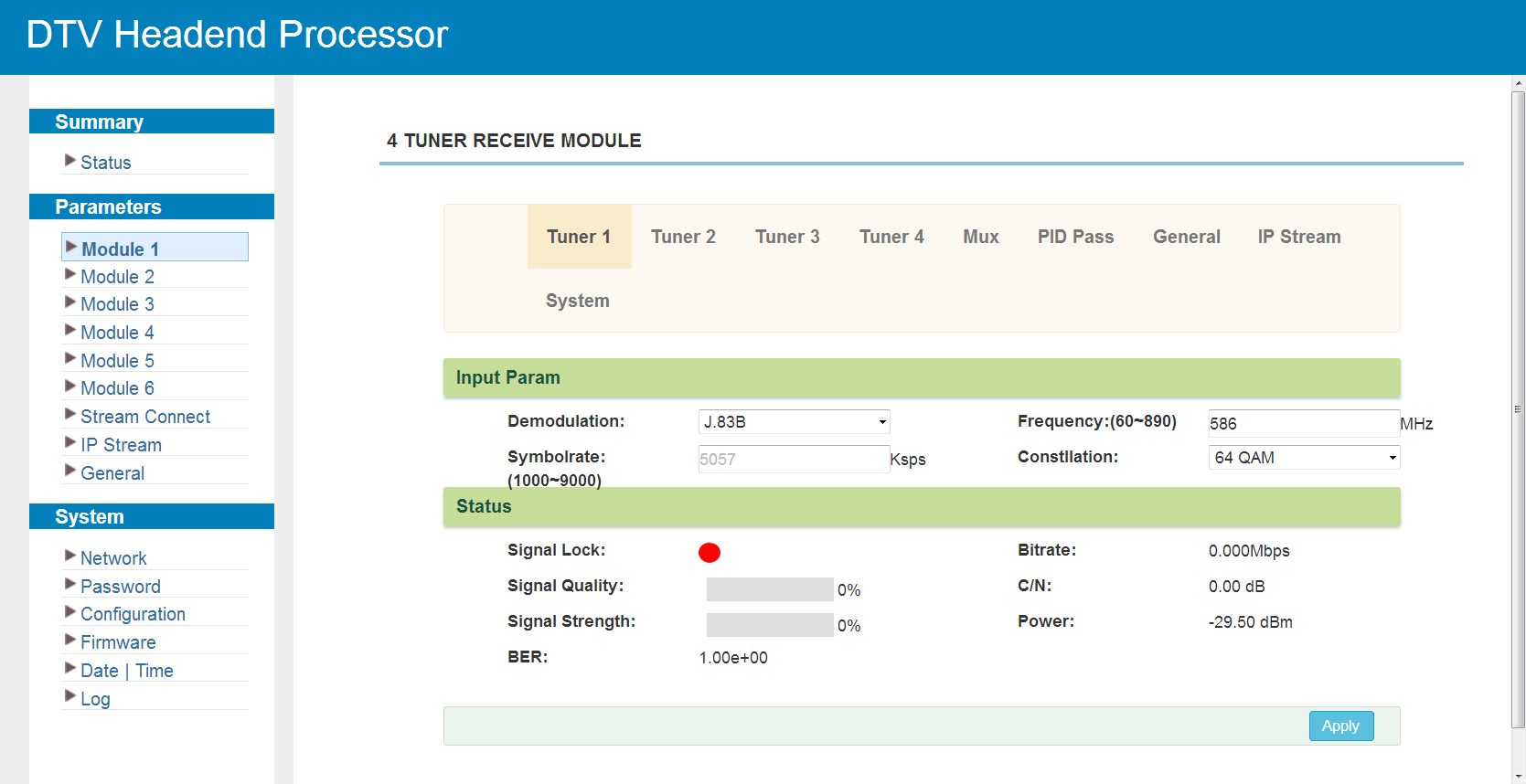
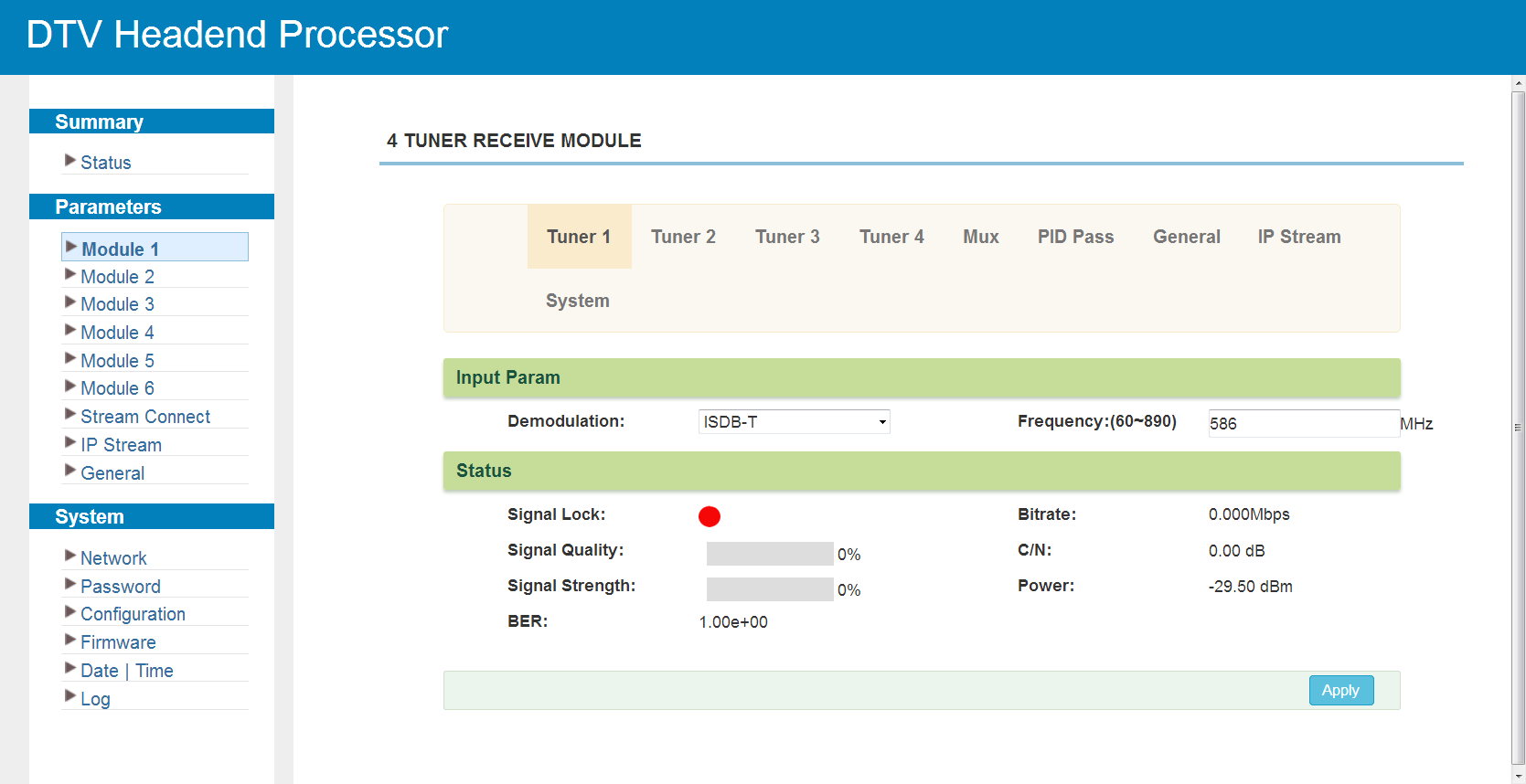
The module supports four tuner inputs with dynamic switching between DVB-C (J.83 A/C), J.83B, DVB-T, DVB-T2 and ISDB-T. Click "Tuner1-4" to set the RF parameters; the form depends on the selected standard.
DVB-C (J.83 A/C):
DVB-T:
DVB-T2:
J.83B:
ISDB-T:
The module has no output ports of its own and is used together with another module. Click "Mux" to select the programs from the four tuners (see Multiplexing Screen):
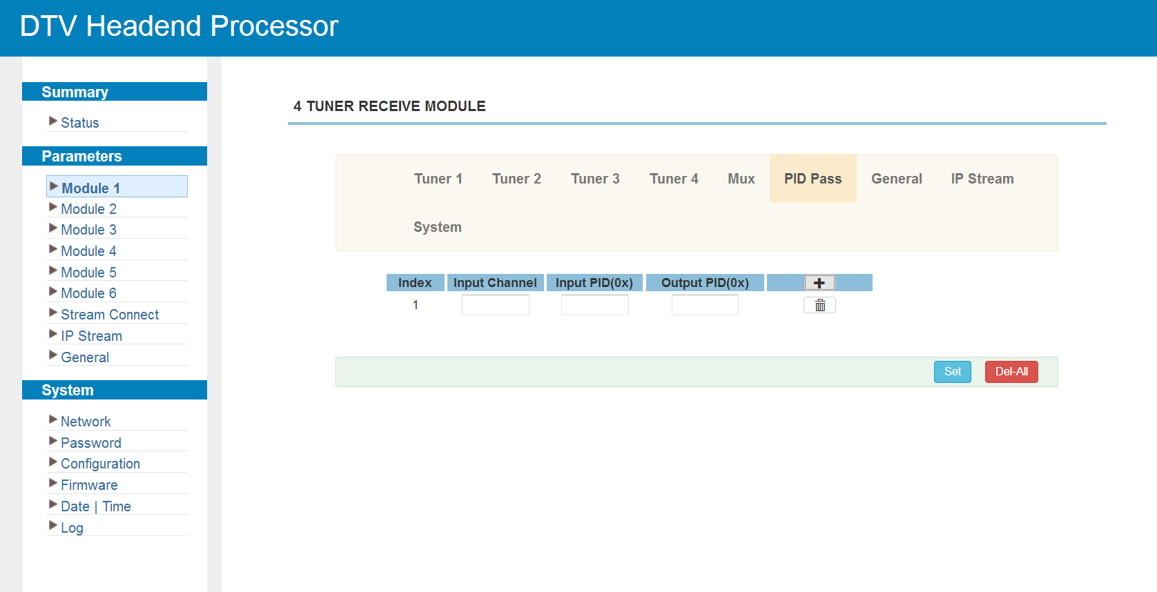
Click "PID Pass" to add the PIDs that must pass through:
Click "General" to set the general parameters of the module:
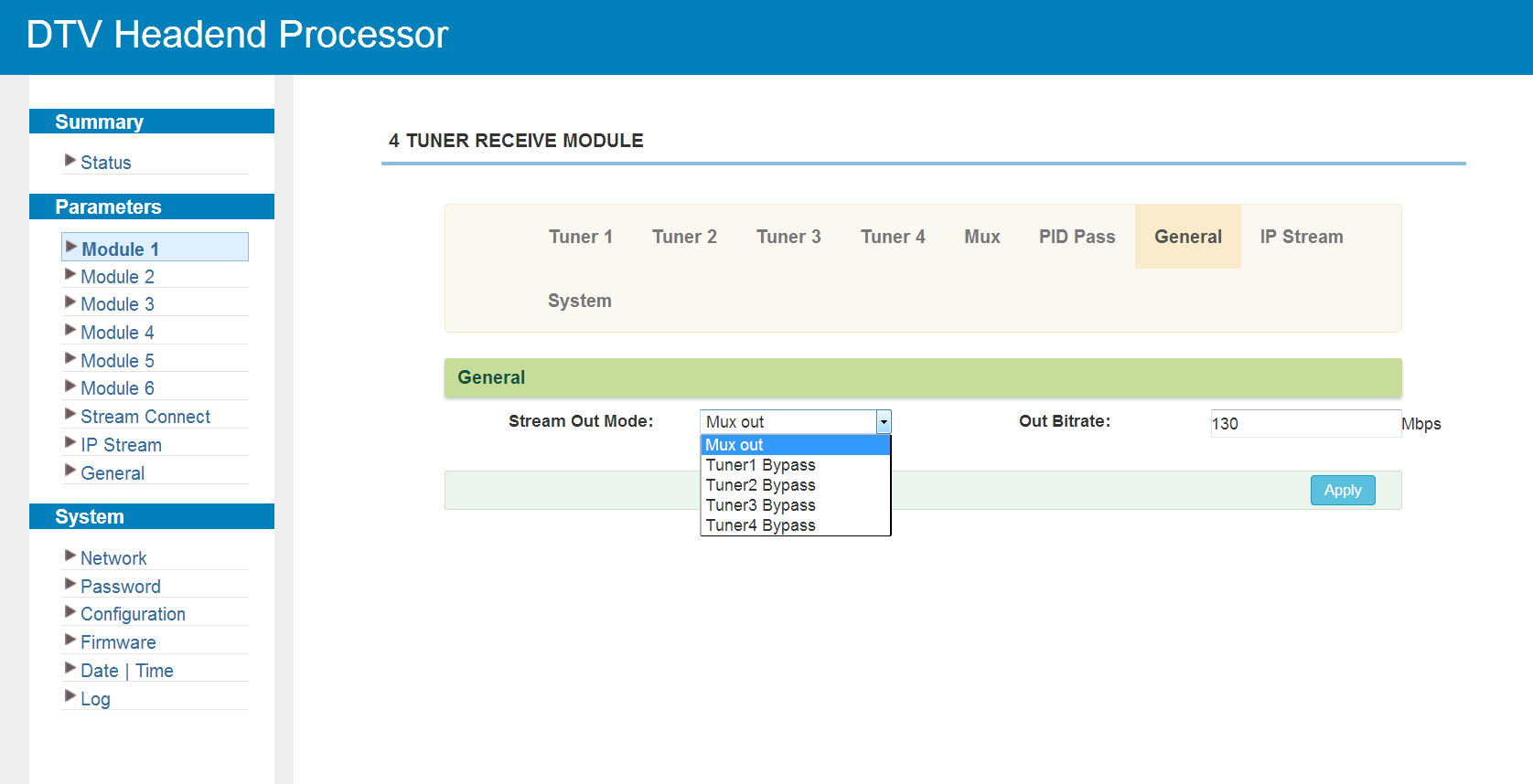
If the stream output mode is set to "Tuner1/2/3/4 Bypass", the multiplexing section stays empty:
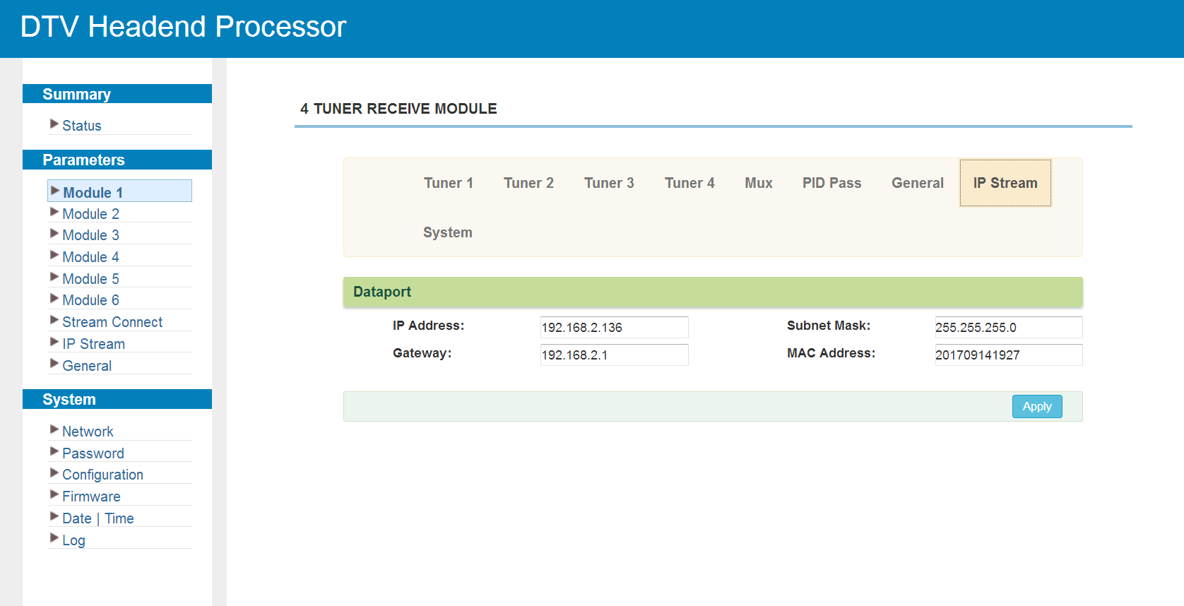
Click "IP Stream" to set the data port parameters:
Click "System" to check the module information:
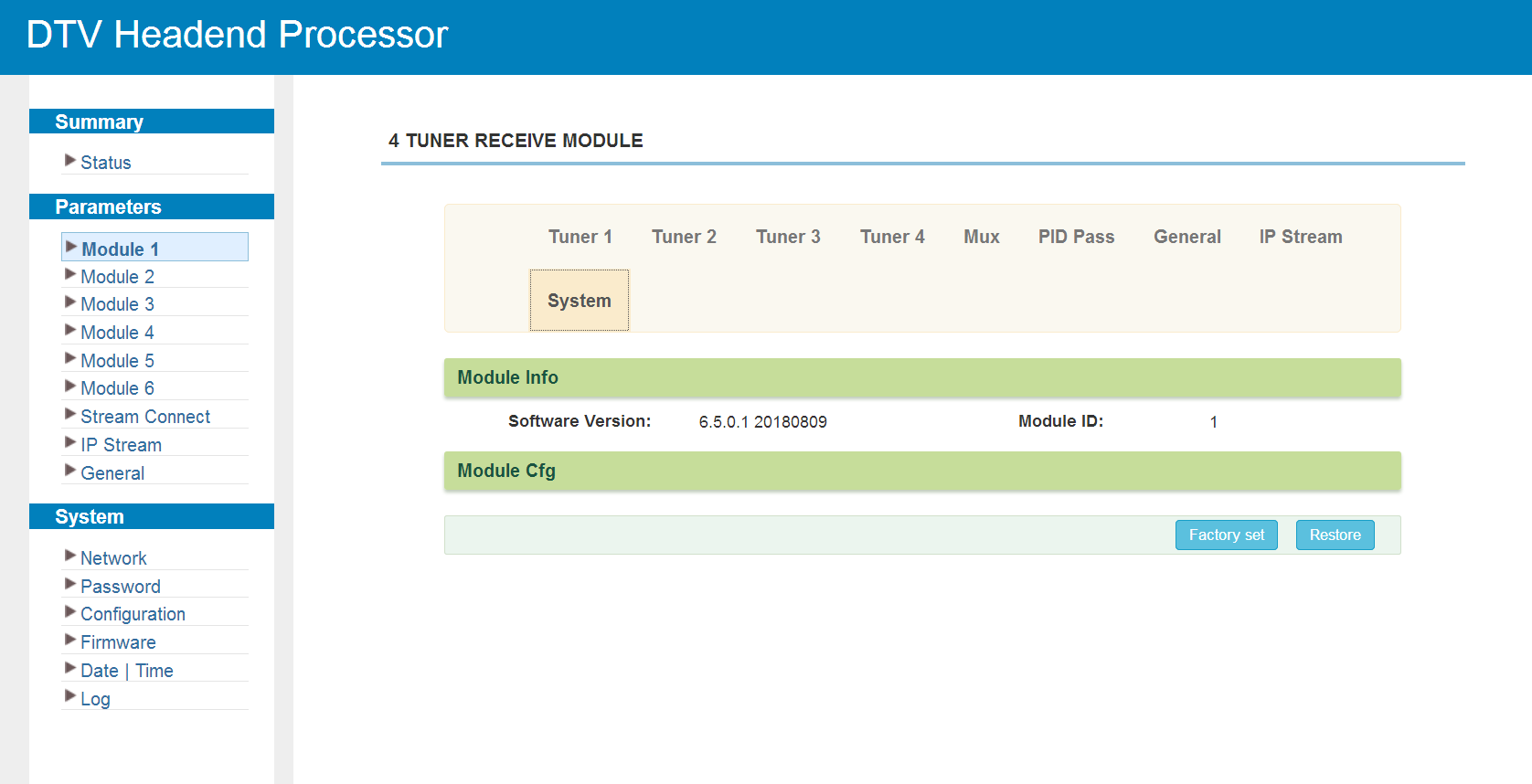
Modulating Modules
The modulating modules — M-MOD-16C, M-MOD-32C, M-MOD-48C, M-MOD-8T, M-MOD-8A and M-MOD-6I — share the same web interface; the number of output channels and the modulation standard differ. The screens below are shown for one of them.
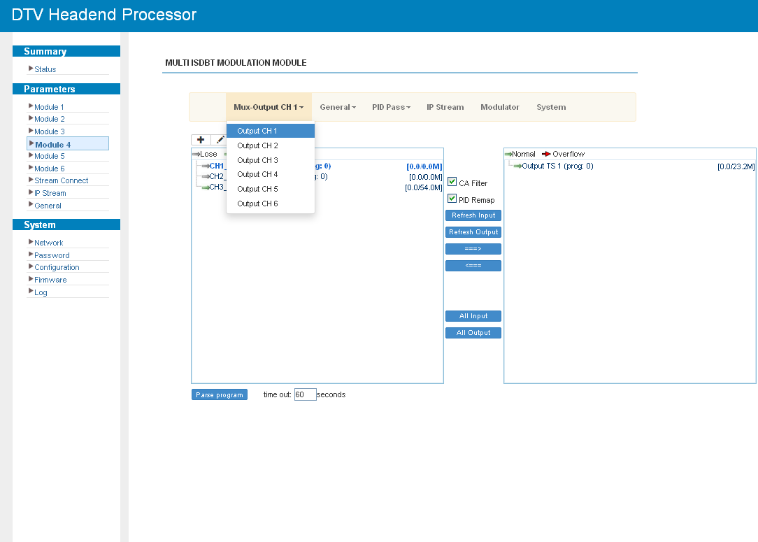
Click "Mux-Output CH X" to select the transport streams for each output channel:
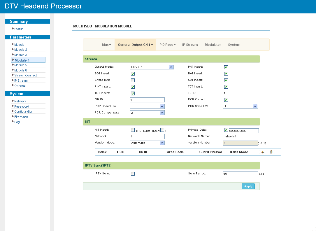
Click "General" to set the parameters of each output channel:
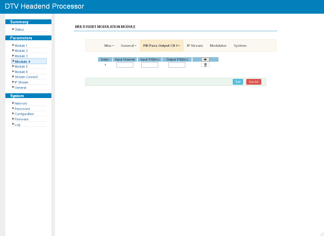
Click "PID Pass" to add the PIDs that must pass through:
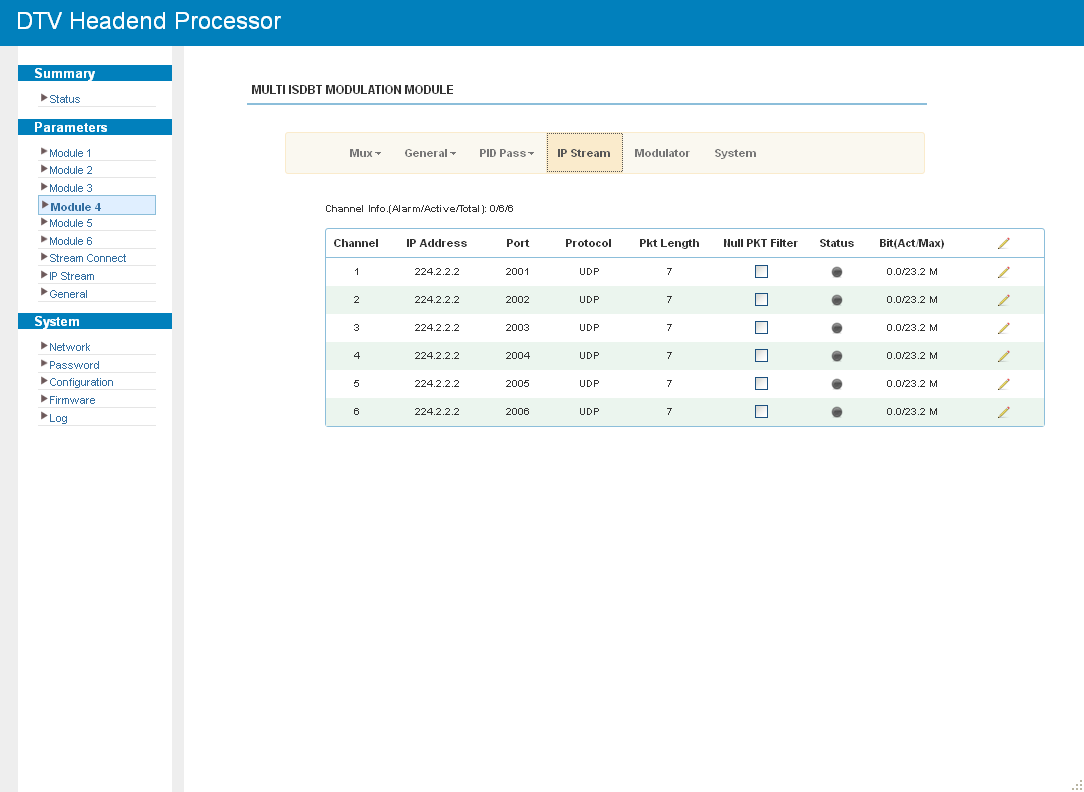
The module can also output the transport streams in IP format through the data port. Click "IP Stream" to set the output parameters:
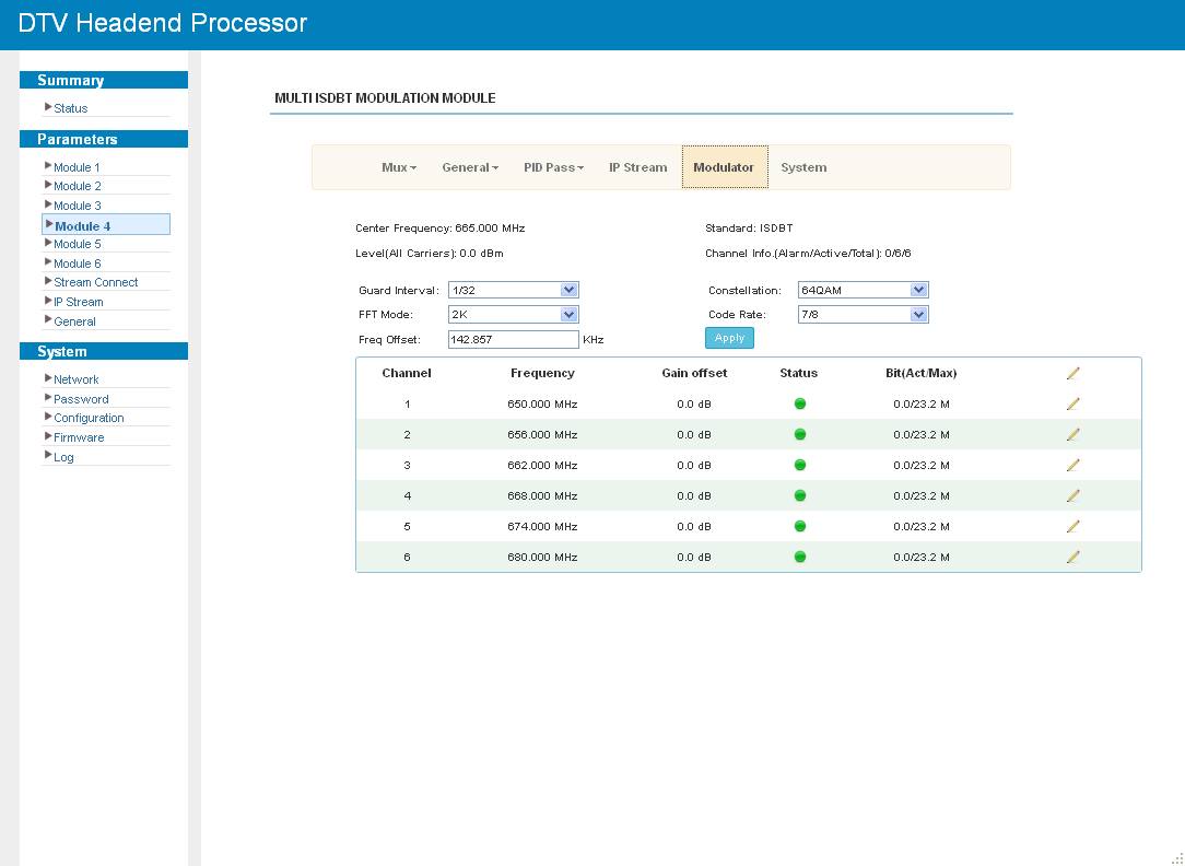
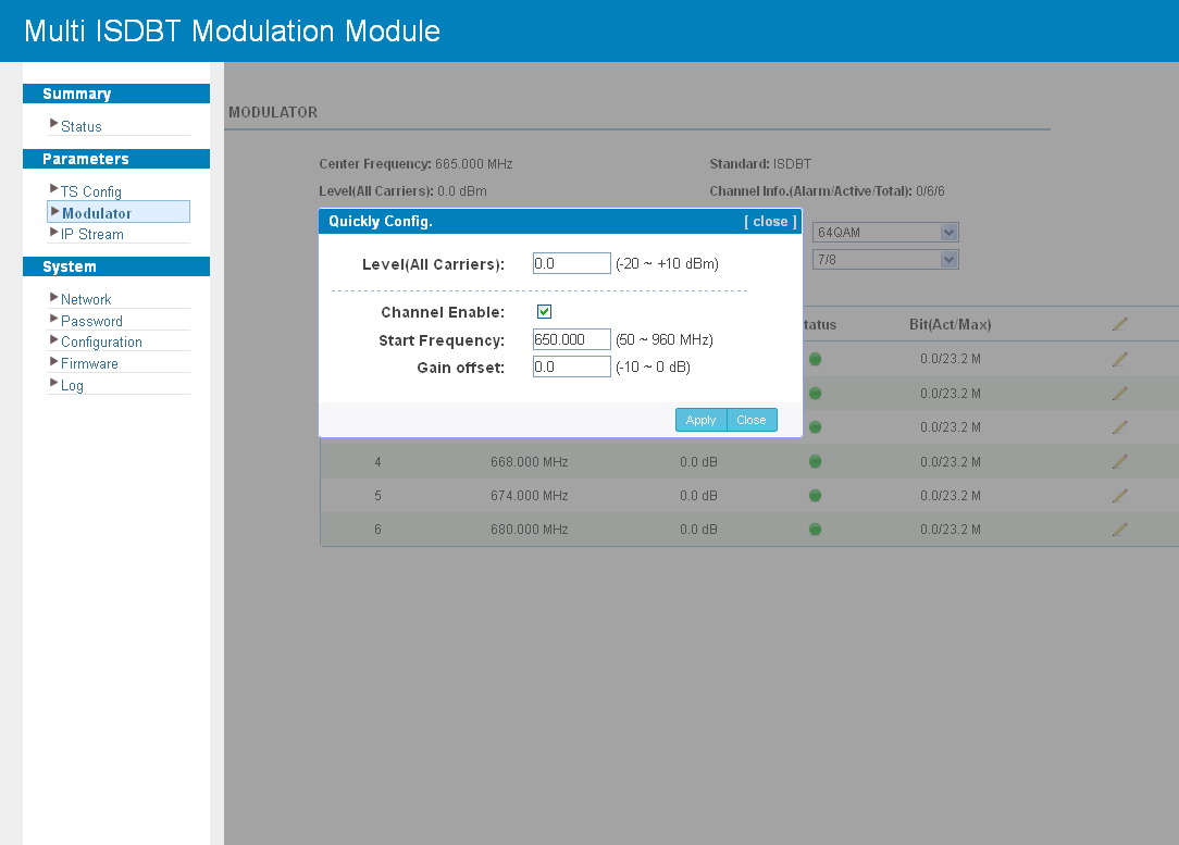
Click "Modulator" to set the RF output parameters. The parameters can be set for one carrier at a time or for all carriers at once.
Click "System" to check the module information:
Decoding and Transcoding Modules
M-DEC-2SDI
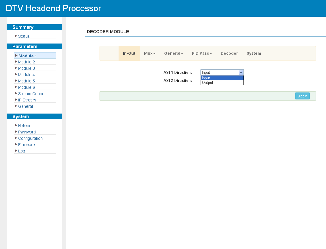
The module has two ASI ports and two SDI outputs. Click "In-Out" to set the direction of the ASI ports:
Click "Mux" to select the programs for the output (see Multiplexing Screen):
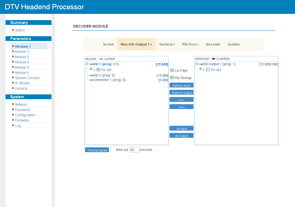
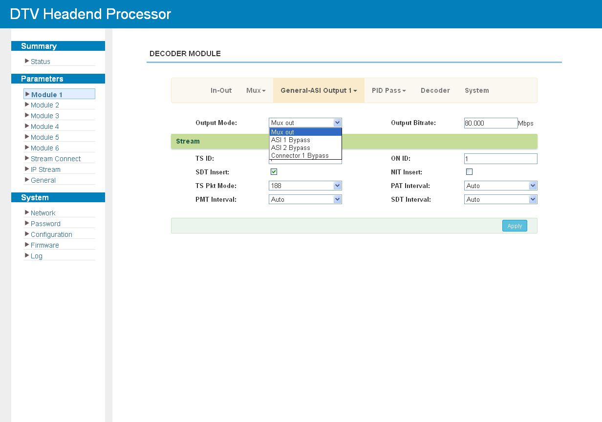
Click "General" to set the parameters of the two ASI outputs and of the module export to the chassis:
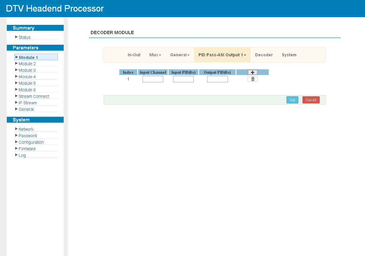
Click "PID Pass" to add the PIDs that must pass through:
The module decodes up to two programs simultaneously to the SDI outputs. Click "Decoder" to configure the video and audio output parameters:
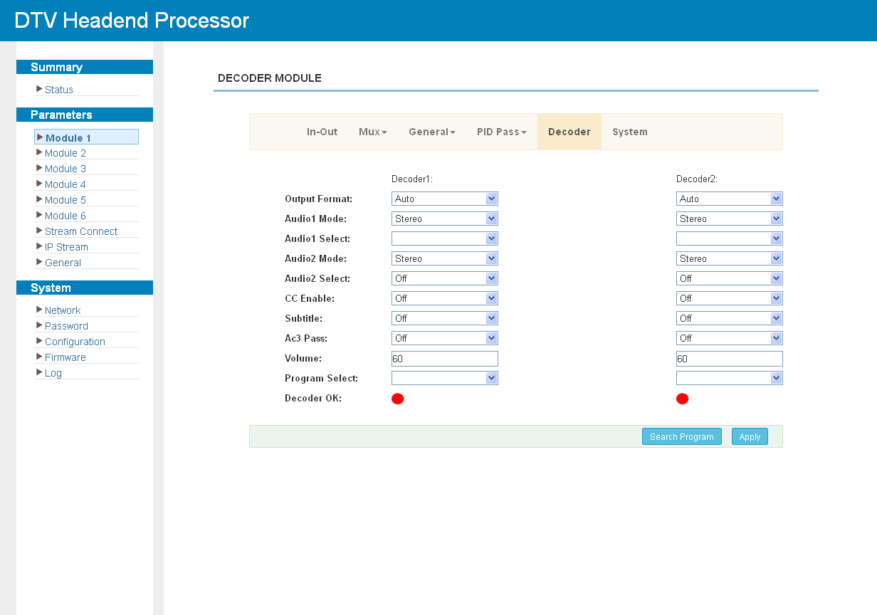
Decoding is configured as follows:
-
Select the decoding channel.
-
Click Parse program to list the available input programs.
-
Set the video and audio parameters and select the program to be decoded.
-
Click Apply and wait until the status indicator turns green.
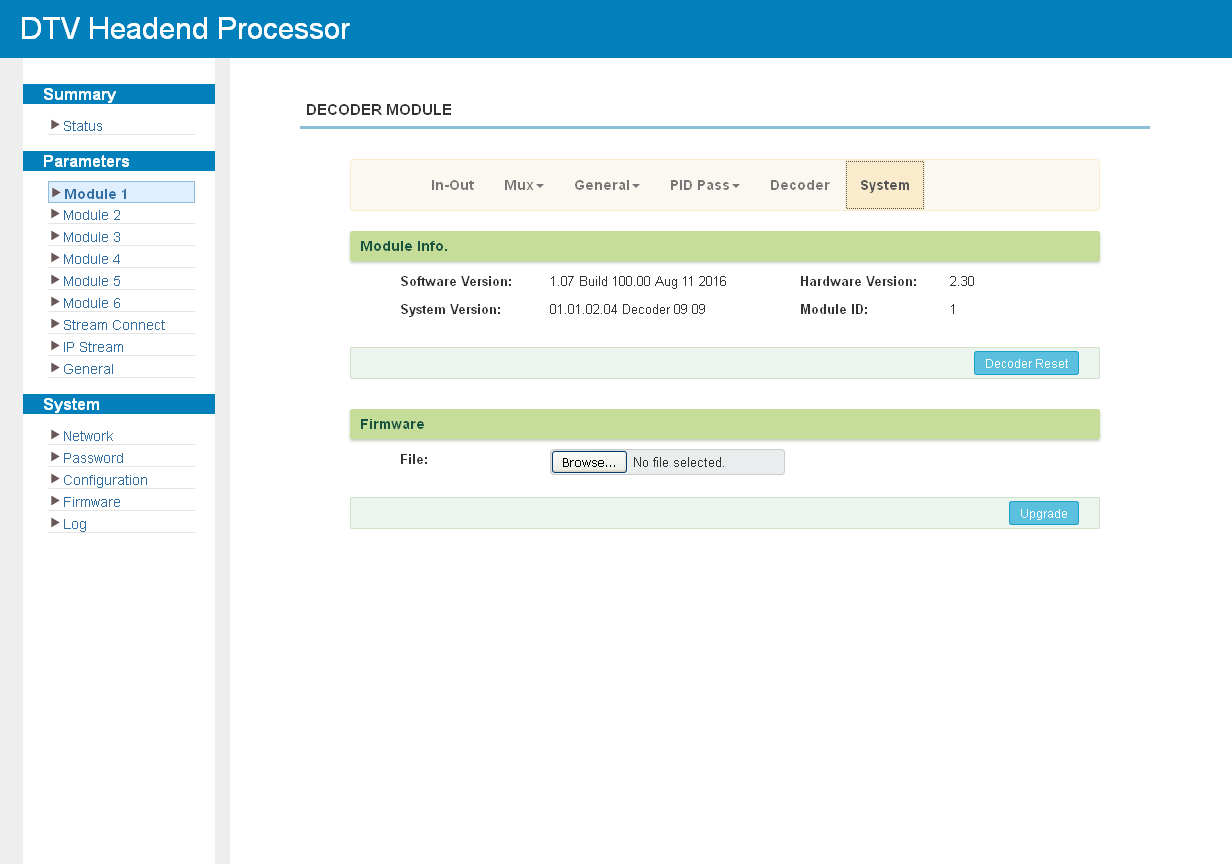
Click "System" to check the module information:
M-TRX-2IP
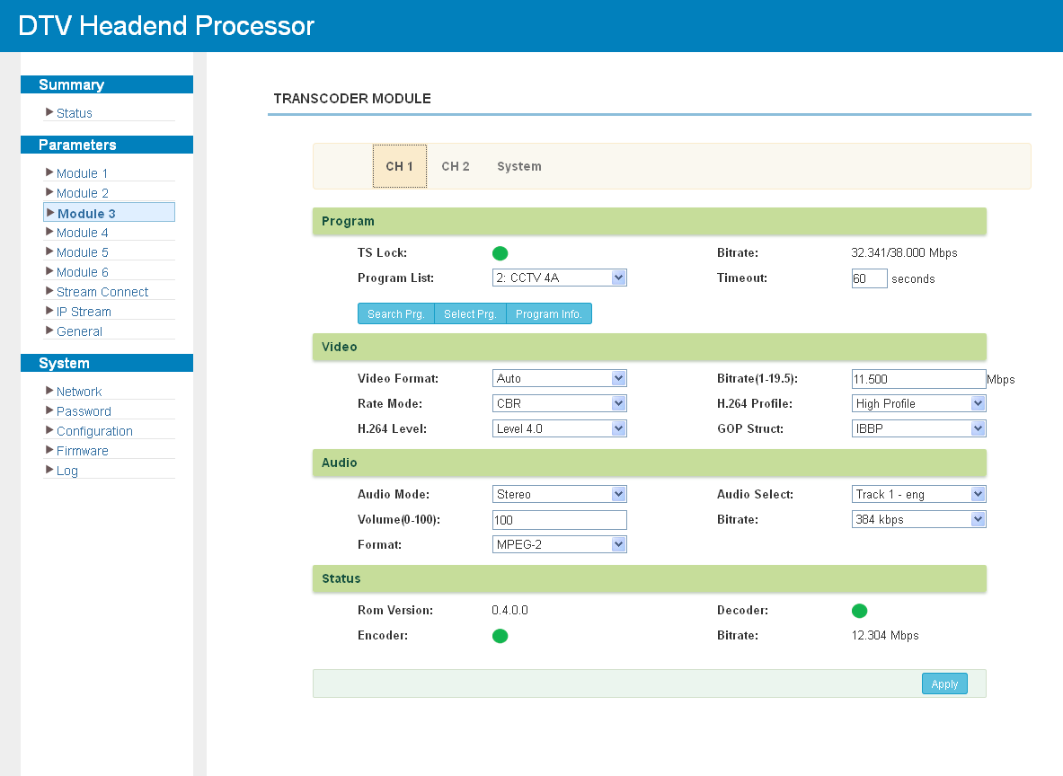
The module transcodes video and audio on two channels. It has no input or output ports of its own and is always used together with another module.
Click "CH1" or "CH2" to set the transcoding parameters:
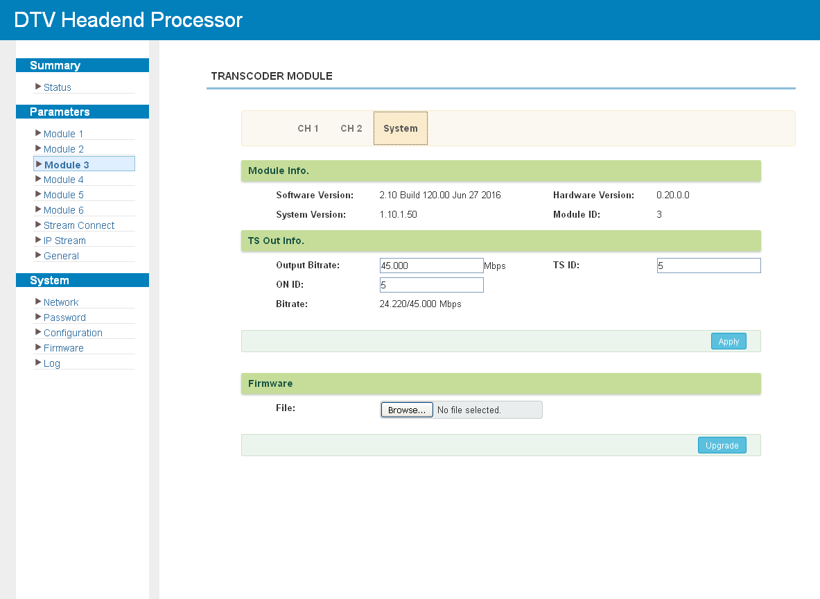
Click "System" to check the module information:
Stream Connect
The chassis combines the streams of the installed modules into the output transport streams. Select "Stream Connect" in the left menu and open the required connector to choose the programs from each module.
The device supports six module outputs, 8 MPTS (through GE2 only) and 512 SPTS (through GE1 only); the ASI output carries the same programs as MPTS 2.
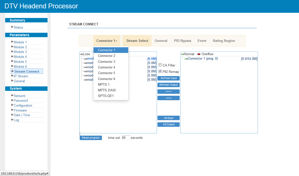
In the input list, "Module X export" means the transport stream coming from module X, and "Connector X" means the stream that will be sent out through module X. The controls of this screen are described in Multiplexing Screen, and program editing in Program Modification.
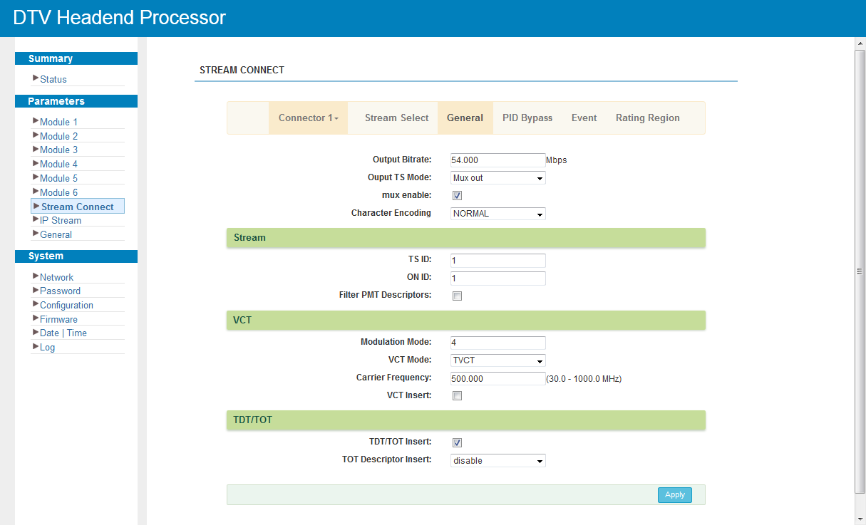
Click "General" to set the parameters of the corresponding connector:
Click "PID Pass" to add the PIDs that must pass through:
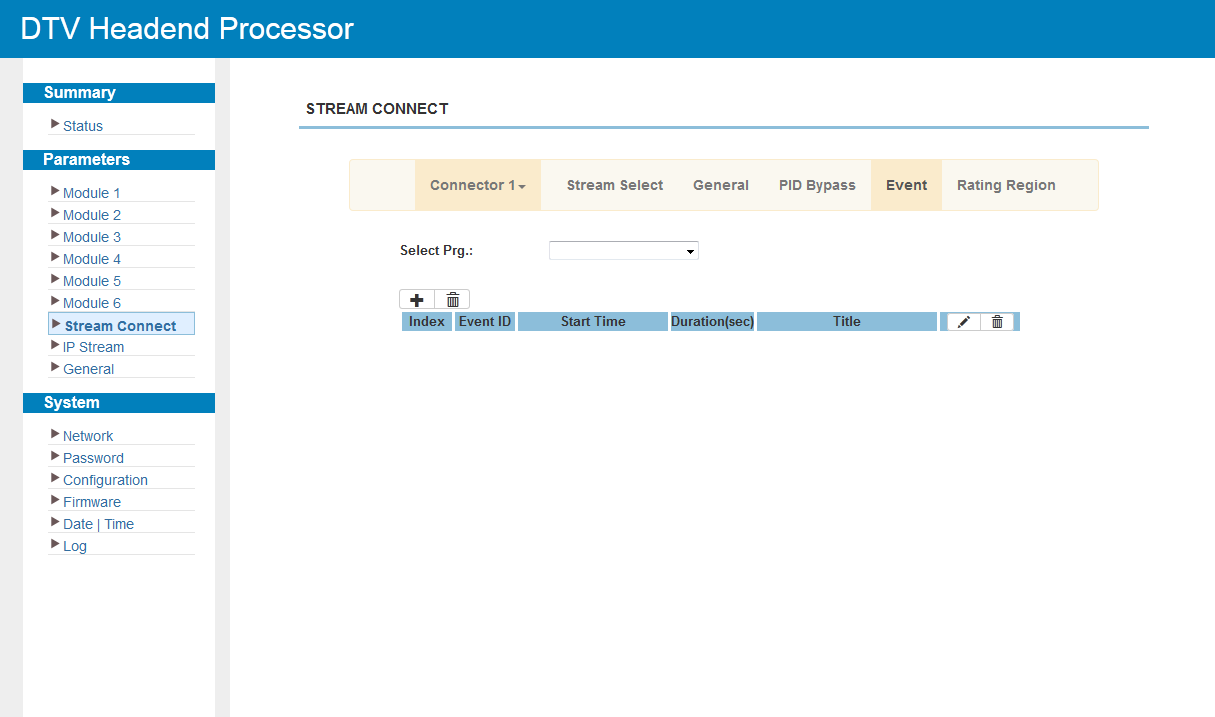
Click "Event" to set the upcoming events for the programs:
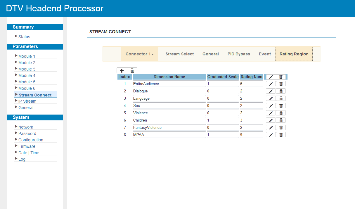
Click "Rating Region" to classify the input programs:
IP Stream
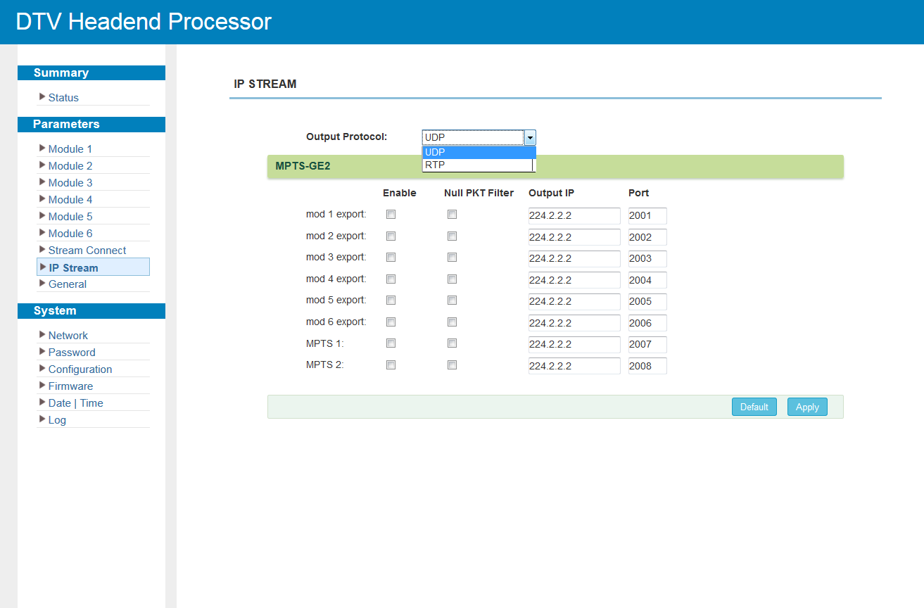
Click "IP Stream" to set the parameters of the transport streams sent out through the data ports: destination IP address, port, protocol and the programs carried by each stream.
General
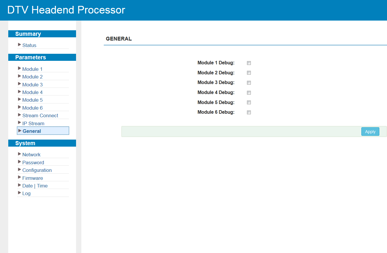
Click "General" to review the general parameters of the chassis.
System
Network
Click "Network" to view and change the network configuration of the chassis: IP address, subnet mask, gateway, web management port and MAC address of the management interface. Click Apply to save the changes.
Password
Click "Password" to change the account and password used to log in to the web interface. Enter the current user name and password, then specify the new ones and confirm. A password of at least six characters that mixes upper- and lower-case letters, digits and special characters is recommended.
Configuration
Click "Configuration" to manage the device configuration: save the current configuration, restore the last saved one, reset to the factory defaults, back the configuration up to a file or load it from a file.
|
|
After restoring a configuration, save it before rebooting; otherwise the restored parameters are lost on reboot. |
Firmware
Click "Firmware" to update the firmware of the chassis; the page shows the current software and hardware versions. Firmware files and update instructions are provided by NetUP technical support on request.
Date / Time
Click "Date/Time" to set the device clock and select the time zone.
Log
Click "Log" to view the device logs for diagnostics. Select the log type from the drop-down list; the log can be cleared or exported to a file.
Troubleshooting
Preventive measures:
-
Install the device where the ambient temperature is between 0 and 45 °C.
-
Ensure good ventilation for the heat sink on the rear panel and other vents.
-
Before switching the device on, check that the input AC voltage is within the power-supply range and that the connection is correct.
-
Check that the RF output level stays within the tolerant range.
-
Check that all signal cables are properly connected.
-
Do not switch the device on and off frequently; the interval between switching on and off must be more than 10 seconds.
Unplug the power cord in the following cases:
-
The power cord or socket is damaged.
-
Any liquid has entered the device.
-
Anything causes a short circuit.
-
The device is in a damp environment.
-
The device has suffered physical damage.
-
The device has been idle for a long time.
-
The device still does not work properly after being switched on and restored to factory settings.
In these cases the device requires maintenance.
Glossary
Abbreviations and professional TV / IPTV terms used in this manual.
| Term | Description |
|---|---|
8VSB |
Vestigial sideband modulation used by ATSC. |
AAC |
Advanced Audio Coding; audio codec (LC-AAC, HE-AAC variants). |
AC3 |
Dolby Digital audio. |
ASI |
Asynchronous Serial Interface; a serial transport-stream interface (over BNC). |
ATSC |
North American digital terrestrial TV standard. |
CA / CAS |
Conditional Access (System); pay-TV access control. |
Carrier |
A single RF channel of the modulated output. |
CATV |
Cable television. |
CBR / VBR |
Constant / variable bit rate. |
CC |
Closed Caption; hidden subtitles. |
Code rate |
FEC coding rate (DVB-T / ISDB-T). |
Constellation |
QAM order (16…256-QAM); higher carries more bit rate but needs a better signal. |
Crypto period |
Interval between scrambling-key changes. |
CVBS |
Composite Video Baseband Signal; analog composite video (single-cable analog video input). |
DAR |
Display Aspect Ratio. |
DB15 / RCA |
Connector types of the CVBS input (the device uses a DB15-to-RCA breakout cable). |
dBm / dBµV |
Units of RF signal level. |
Dialog normalization |
Loudness-levelling metadata that keeps the perceived volume consistent across programs (Dolby Digital / AC-3). |
DTS |
Decoding Time Stamp; a decoder timing marker — the "DTS Delay" setting tunes end-to-end latency (not the DTS audio codec). |
DVB-C / DVB-T |
Digital cable / terrestrial TV standards. |
DVB-CSA |
DVB Common Scrambling Algorithm. |
ECM / EMM |
Entitlement Control / Management Message — descrambling keys / subscriber rights. |
ECMG / EMMG |
ECM / EMM generators; the interface to the CAS. |
EIA-608 / EIA-708 |
Closed-caption standards (CEA-608 / CEA-708); carried on the SDI input (Line 21). |
FEC |
Forward Error Correction. |
GE |
Gigabit Ethernet port. |
GOP |
Group of Pictures (I / P / B frame structure). |
Guard interval |
OFDM guard interval (DVB-T / ISDB-T). |
H.264 (AVC) / H.265 (HEVC) |
Video codecs; HEVC is more efficient and is used for 4K. |
HDMI |
Digital video input. |
HP / MP / BP |
High / Main / Baseline Profile — H.264 complexity / efficiency tiers. |
IGMP |
Internet Group Management Protocol; multicast subscription. |
IP / UDP / RTP / RTSP |
Stream delivery: IP network; UDP (no acknowledgements); RTP (media over UDP); RTSP (playback control). |
ISDB-T |
Japanese digital terrestrial TV standard. |
J.83 A/B/C |
ITU-T DVB-C variants (A — Europe, B — USA, C — Japan). |
LCN |
Logical Channel Number; channel position in the receiver’s list. |
Low Delay |
Encoder mode that minimises the end-to-end latency from the encoder to the decoder. |
MER |
Modulation Error Ratio; signal quality, in dB. |
MPEG-1 Layer 2 / MPEG-4 |
Audio / video coding standards. |
MPTS / SPTS |
Multiple / Single Program Transport Stream. |
Multicast / unicast |
Group (one-to-many) / addressed (one-to-one) delivery. |
NIT |
Network Information Table; network parameters (frequencies, modulation) used by receivers for scanning. |
NMS |
Network Management System; the device’s web management interface. |
NTP |
Network Time Protocol; time synchronisation. |
NTSC |
National Television System Committee; analog colour-TV standard (M / J variants). |
Null packet |
Stuffing TS packet (PID 0x1FFF) used to keep a constant bit rate; can be filtered on output. |
OSD |
On-Screen Display; graphic overlay (logo / QR code). |
PAL |
Phase Alternating Line; analog colour-TV standard (B / D / G / H / I variants). |
PCR |
Program Clock Reference; timing reference for decoder synchronisation. |
PID |
Packet Identifier; addresses video / audio / data within a transport stream. |
PID remapping |
Reassigning output PIDs to avoid conflicts between streams. |
PMT |
Program Map Table; the PSI table listing a program’s video / audio / data PIDs. |
PSI / SI |
Program Specific / Service Information; the signalling tables of a transport stream. |
QAM |
Quadrature Amplitude Modulation. |
QPSK |
Quadrature Phase-Shift Keying (DVB-T / ISDB-T). |
RF |
Radio-frequency output. |
RS (204, 188) |
Reed–Solomon forward error correction used in DVB. |
SD |
Standard Definition (e.g. 720×576i / 720×480i). |
SDI |
Serial Digital Interface; professional video. |
Service ID |
Service (channel) identifier within a transport stream. |
SFP |
Slot for an optical or copper transceiver. |
Simulcrypt |
Scrambling by several CA systems at the same time. |
Symbol rate |
Modulation symbol rate (Msps / Ksps). |
Teletext |
Teletext. |
Transmission mode (2K / 4K / 8K) |
Number of OFDM carriers (DVB-T / ISDB-T). |
TS |
Transport Stream; the MPEG-2 container for audio / video and signalling. |
VCT |
Virtual Channel Table; channel signalling used in ATSC / J.83B networks. |