Quick start
Before you start the NetUP Streamer:
-
check the numbering of streamer inputs,
-
connect the coaxial cables to streamer inputs on its rear panel and the Ethernet cable to the port on its front panel,
-
plug in the device.
Launch the web interface of NetUP Streamer. Log in and open NetUP DVB IP Streamer module to configure inputs and set up streaming. The following articles will be helpful for you in setting up:
Numbering of NetUP Streamer inputs
NetUP Streamer headend stations are presented in three models: Streamer mini, Streamer 8x and Streamer 16x.
Depending on the model, the streamer can support 4 to 16 inputs and CAM modules. The inputs in the web interface are numbered as inputs of your device. Inputs located on the rear panel of NetUP Streamer and numbered as follows:


First launch of the web interface
Make sure that the satellite signal cables are connected to the streamer inputs, the Ethernet cable is connected to the 1st port on the front panel of the streamer and the device is plugged in.
Open a browser and write the default IP address: 10.1.0.1.
On the opened page enter the default login and password: admin and netup123
As result, the Home page opens. It contains the values of the main server parameters and links to modules included in your license.
|
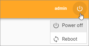
It is strongly recommended to change the password immediately after the first log in. To do it, click on the user name in the upper-right corner of the Home page and select Change password |
The Server settings module is available for any configuration. Go to this module, select the Network page and expand the eth0 panel.
|
The network adapter №1 on the front panel of the NetUP streamer is the eth0 in the web interface, №2 – eth1, №3 – eth2, №4 – eth3 |
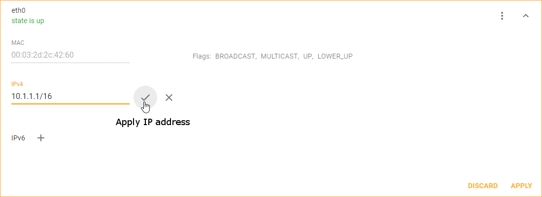
Enter your IP address, save it and then restart the server.
Run the web interface again and specify the IP address you set.
Log in and go to the Server settings module. Open the License page and upload your license.
Then open the Modules page to upload modules you got with your license. If necessary, update the modules.
When the update is complete, go to configure streamer inputs.
How to get transponder settings?
In the web interface go to the NetUP DVB IP streamer module.
On the NetUP DVB to IP gateway page select an input and expand its panel to configure it.
You can set input parameters manually, get them from a satellite database or browse network, and also upload them from a preset.
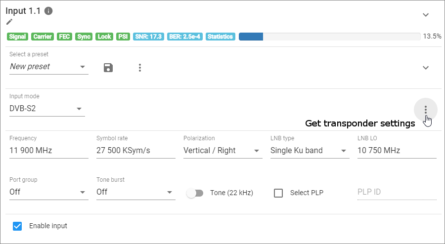
To set parameters manually, select Input mode (DVB-S, DVB-S2, DVB-T, DVB-T2, DVB-C Annex A, ISDB-T) and fill in all the fields in a form. Each of input modes has its own set of fields, and the list of available modes depends on the DVB adapter type.
In the right corner of the form, press the menu button and select Satellite database to get the transponder settings. In the opened window, select one of available transponders to fill in the form using its parameters.
|
If you connect a CAM (Conditional Access Module) to the corresponding streamer input and select the DVB-S or DVB-S2 mode for it in the web interface, the Browse network will be available for this input |
Make sure that all the fields are filled in correctly and check the Enable input box. To active the settings, click on APPLY.
If the input panel displays quality indicators at the top and a list of programs at the bottom, you can go to set up streaming.
How to set up streaming?
In the web interface go to the NetUP DVB IP streamer module.
On the NetUP DVB to IP gateway page select a configured input and expand its panel, then go to a list of programs. In the list, opposite one of the programs, click on ![]()
In the opened Stream setup window add the required number of streams and set up parameters for them.
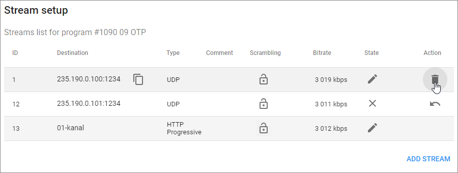
You can use following stream types: UDP, UDP IPv6 and HTTP Progressive. Each type of stream has its own set of parameters. If you need to add several streams of the same type for one program, we recommend adding a two-digit number in the Address field to the last digit in the fourth octet, which is one more than the previous one. For example, if the address of the 1st stream is 235.114.3.1, then the address for the 2nd stream can be 235.114.3.101, and for the 3rd one – 235.114.3.102. In this case it is easier to avoid IP address conflict.
To save changes and close the window, click on APPLY.
Select the next program from the list and set up streaming in the same way.
|
To control all streams for one program in a single dialog, open Interface options on the NetUP DVB to IP gateway page and turn on the corresponding option |
How to use presets?
Configure one of the streamer inputs, select New preset and click on ![]()
In the opened dialog write a name of the preset and save it.
If the input has configured streams, their parameters will save to the preset. When you want to use such a preset, you can select: Apply input settings or Apply both input and streaming settings
|
When loading the streaming settings, the system compares addresses of the existing streams with stream addresses that need to be downloaded from the selected preset. If the system finds identical addresses, it will generate an error and stop broadcasting streams which were downloaded from the preset |
To configure an input using a preset, select the preset from the list and when the web form displays input parameters click on APPLY.
You can modify parameters before applying them. Modifying in the web form will not edit the preset.
To edit a preset, select it from the list, change settings for the input or the streaming or both, apply the changes and then click on ![]()
to the right of the preset. In the opened dialog you can edit the preset name and save all the changes.
LCD panel
Launch
Before you start the NetUP server, plug the network and power cables into the device and then switch power on.
After starting, the LCD screen displays Starting… or Startup…. It depends on a model of your device. Then the screen indicates the total rate of input and output traffic.
Screens
Use Up and Down buttons to move from screen to screen:
-
Reboot system
-
Shutdown system
-
Generate (Reset) password Use Enter button to shut down, reboot the device or generate a new password.
-
IPTV [CPU]v

First number is the total CPU load. Three subsequent numbers give, correspondingly, the portions of CPU load related to user tasks(u), system tasks(s), and awaiting data from the peripherals (w).
-
Network setup. See the following article to learn how to set IP address and subnet mask.
How to set IP address and subnet mask?
-
Use Up and Down buttons to move to the Network setup screen and press Enter.
If your device does not display the Network setup screen, press Fn button on any statistics screen and then press Enter. The network configuration screen will appear.
-
Press Up and Down buttons to select the network interface, then press Enter.

-
Press Enter to select an octet for editing and then press Up or Down to change it. The selected octet will be indicated by a symbol " > ".
-
Select the last octet of the IP address and press Enter to go to edit the subnet mask.
-
Press Up or Down to increase or decrease the number of mask bits and press Enter to go to the save dialog.
-
Use Up and Down buttons to select one of the following options: Save changes – to save IP address and subnet mask, Discard – to cancel changes. The selected option is emphasized with brackets. Press Enter to confirm the selection.
Add the entry to the configuration file of your DNS server that the entered IP address is associated with
mw.iptv
Server settings module
Launch the web interface of NetUP.tv. Log in and click on the corresponding button on the Home page to go to the module and set up the server.
The side menu of the module allows access to the following pages:
To hide or show the side menu, click on ![]()
To go back to the Home page, click on Home
Modules
There are two tabs on the page: Modules and Services.
Module contains a certain set of functions that are responsible for the operation of a NetUP.tv component, for example, dvb-gw is responsible for the operation of NetUP DVB IP Streamer.
Service is a utility that is responsible for starting or stopping a module.
Use the Modules tab for the following actions:
-
Install or update modules either individually or all together.
-
Uninstall a module or view the full information about it.
-
Upload a module.
|
Drag your files to the web page and the upload dialog will open automatically |
After uploading and installing a new module, go to the tab Services to run this module. Click on the corresponding button in front of the service responsible for the module, and then confirm the action in the window that opens. Similarly, you can stop some services if you do not plan to use corresponding modules.
Firmware
Open this page to upload, install or delete a firmware.
|
Drag your files to the web page and the upload dialog will open automatically |
Firmware of different versions of the NetUP.tv system may not be consistent with each other.
If you need to downgrade to previous firmware releases, contact the NetUP technical support department
|
Please note that you can upload incompatible firmware and it will appear in the list. A warning message will appear only when you try to install this firmware |
Backup
The NetUP.tv system provides automatic backup once a day.
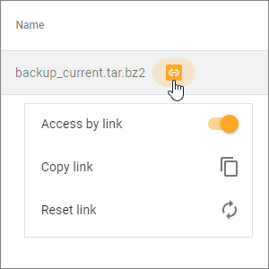
Backups are tar.bz2 archives that contain the system settings.
The latest automatic backup is available for download at the link. You can open or close access to the archive, as well as copy or reset the link.
To create or upload backup , click on  in the lower right corner and select an action.
To restore system settings, select an archive, click on ![]() and confirm the action in the window that opens.
and confirm the action in the window that opens.
|
Before restoring a backup, make sure that the backup was NOT created during the period when you used the firmware related to the another release. The release number is the first two digits of the product version, for example, 2.0, 2.2, etc. |
License
Open this page to get information about uploaded licenses (license numbers, components, expiration dates and restrictions) or to upload a new one.
To update a license, click on 
In the opened window, select the files you want to load, or drag them, wait for the download to finish and close the window.
|
Before uploading a new license, make sure this license is fully compatible with the old one |
Connections
Open this page to see all NetUP.tv systems. Each of the systems has a separate panel. The panel displays a list of services with which interaction is possible. Addresses of interacting services are links.
Expand a panel and click on the pen icon next to the service you want to edit. In the opened window write the address manually or check Auto detect box to detect the address automatically, then click on Save.
Network
Open this page if you want to:
-
Configure interfaces which are related to the network interfaces on the front panel of your streamer. The №1 network interface on the streamer front panel is the eth0 in the web interface, №2 – eth1, №3 – eth2, №4 – eth3

-
Enable or Disable NetUP support tunnel
Each of the interfaces, DNS and NetUP support tunnel has a panel. Expand a panel to access the settings.
Configure interfaces
An interface settings panel has a list of the IP addresses assigned to this interface and buttons to add IPv4 and IPv6 address. Click on one of the buttons to add IP address or click on an existing address to edit it. Write or edit the address, click on ![]() , and then click on APPLY.
, and then click on APPLY.
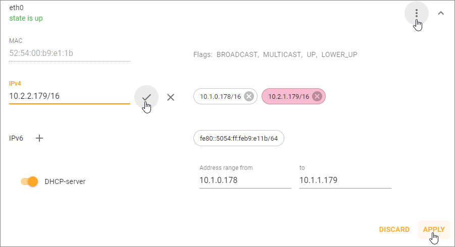
If IP address is not the main or the last remaining IP address, you can delete it. Click on ![]() next to the IP address and click on APPLY at the bottom of the panel.
next to the IP address and click on APPLY at the bottom of the panel.
|
You cannot delete the address assigned for the main interface. It is used for the component’s interaction and thus is absolutely crucial for the system’s operation. The default main interface is eth0 |
To remove interface configuration, click on ![]() and select the corresponding option.
and select the corresponding option.
Under an interface name you can see its status: UP – the network cable is connected and the interface is configured or DOWN – the interface is not configured. If some interface is not configured, click on ![]() and create an empty configuration for it to see whether the cable is connected to the corresponding interface on the streamer front panel.
and create an empty configuration for it to see whether the cable is connected to the corresponding interface on the streamer front panel.
Create VLAN, VTUN, BOND
To create a virtual interface, click on  at the bottom of the page and select one of the following types: VTUN, bond or VLAN. In the opened dialog fill in the fields and click on CREATE.
To delete a virtual interface, expand its panel, click on ![]() and select Remove interface configuration.
and select Remove interface configuration.
Routing
The page contains two lists of routing rules: System routing rules and User routing rules. You can edit, add or remove user routing rules. The system routing rules are needed for correct system operation and can’t be edited.
Users & Roles
There are two tabs on the page: Users and Roles.
Use the Users tab for the following actions:
-
Add a new user.
-
Delete users or change their passwords.
-
Assign roles to users, i.e. configure access rights for them.
To create and configure a role, go to the Roles tab.
Time
Open this page to set the date and time of your server, as well as select your time zone.
|
Set the correct time zone before uploading the license. Time zone changes after the server reboot |
In the web interface, you can enable time synchronization with the time server of your choice. Date and Time are synchronized with debian.pool.ntp.org by default
DVB IP Streamer module
Launch the web interface, log in and click on the corresponding button on the Home page to go to the module.
Use the NetUP DVB IP Streamer module to configure the streamer inputs and set up streaming. To go back to the Home page, click on the arrow to the left of NetUP DVB to IP gateway.
NetUP DVB to IP gateway
The NetUP DVB to IP gateway page is divided into panels. The number of panels corresponds to the number of physical inputs on the rear panel of your streamer. The inputs in the web interface are numbered as inputs on the rear panel of your device.
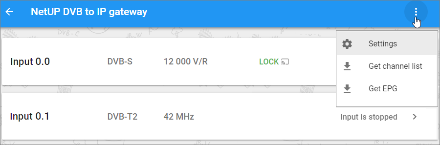
Click on the menu button at the top of the page to get channel list or EPG, as well as to open the settings window with user interface options. Use the User interface options window to change the interface language, enable interface tutorial that launches a brief description of the page functionality, and to switch some options.
Expand an input panel to get transponder settings.
If an input is configured, its panel displays:
Signal quality indicators
The status of the indicators changes after each update of the input signal parameters.
Signal |
presence (green) or no signal (red) |
Carrier |
presence or no carrier |
FEC |
presence or no error correction |
Sync |
successful synchronization of the adapter with the signal (green) or a problem (red) |
Lock |
successful capture and decoding of the video signal or a problem |
PSI |
stream identifiers and the state of service tables: PAT, PMT, SDT, NIT, EIT, and etc. Click on the indicator to see more |
SNR |
the signal to noise ratio |
BER |
the bit error rate |
Statistics |
transport stream statistics. Click on the indicator to see more |
Signal strength |
signal strength in percent |
Input parameters
Select an Input mode (DVB-S, DVB-S2, DVB-T, DVB-T2, DVB-C Annex A, ISDB-T) and the panel will display a set of parameters for the input. Each of input modes has its own set of parameters. Set the values for the parameters and click on APPLY.
|
See the specification of the converter you are using to get LNB frequencies |
For DVB-S2 and DVB-T2, the Select PLP option is available. PLP (Physical Layer Pipe) is a logical channel that may carry one or multiple services. You can specify the ID of the channel that you want to receive in the corresponding field.
CAM parameters
If you connect a CAM (Conditional Access Module) to your streamer, the input panel will display following indicators:
-
The CAM state (present or missing) and its name
-
The list of opening sessions (RM, AI, CA, MMI)
-
The CAM menu (settings and information about CAM and smart card)
-
The CAM message log
If CAM works normally, the following sessions are always open:
RM |
Resource manager |
AI |
Application information |
CA |
Conditional Access Support |
Click on AI and CA indicator to see more details about CAM (name, manufacturer, supported hiding systems).
|
If any of these sessions is missing, then the CAM is broken |
Other sessions that may be open:
MMI |
Man-Machine Interface |
It opens when you open the CAM menu |
DT |
Date-time |
CAM requests the date and time of the streamer |
Click on MMI to close MMI session.
|
Read more about DVB CA sessions and resources in EN50221. There is no need to study the standard for initial troubleshooting |
Stream setup
The bottom of the input panel displays a list of received programs.
Click on a program number to see program properties or click on a program name to see the names of the programs: the one that is on the air and the next one.
Opposite each of the programs in the list you can see the status of this program. If the lock is closed, it means the stream is encrypted, if the lock is open, it means the stream is decrypted. Click on the key icon at the top of the list to open the Test descrambling dialog where you can select the programs for checking the decryption option.
Click on the ![]() opposite of the program to set up streaming
opposite of the program to set up streaming
FAQ
How to grant access to the server?
If you need to provide NetUP support with access to your server, follow these steps:
-
Make sure your server has internet access. The server can be connected to the Internet directly or through an intermediate server.
-
Choose one of the ways to provide access to your server and do the necessary preparatory steps.
Tunnel (recommended way)
-
Log in to the web interface of the server you want to provide access to, go to the Server settings module and open the Network page.
-
Expand the NetUP support panel and specify Host and Port, then enable the tunnel.
Before specifying a port, make sure that access to it is allowed.
If you selected tuns.netup.tv, make sure that DNS is configured correctly. -
Notify NetUP support that you have enabled the tunnel and give the following information:
-
the Local IP which will appear on the NetUP support panel after enabling the tunnel;
-
credentials for access;
-
the number of your license.
-
Public IP
-
Make sure that 22 and 80 TCP ports are available.
-
Check the reliability and, if necessary, change the password to access your server.
-
Give the following information to NetUP support:
-
the public IP address of your server;
-
credentials for access.
-
-
How to use a debug cable?
When a network connection to the NetUP server is impossible, use the debugging cable supplied with the server. Connect the port on the server’s front panel to the COM port on any PC and open a terminal program. A Linux console will show up in the terminal window.
Use the following connection parameters:
Speed (bit/s) |
19200 |
Data bits |
8 |
Parity |
None |
Stop bits |
1 |
Flow control |
None |