4
NetUP MultiMedia Processor (transcoder server) web interface allows to edit basic server settings (network settings, administrator’s password, etc.) and to manage transcoding.
To access the web interface, enter an IP address of Middleware server in your browser's address bar. On the opened page enter the login and the password specified in the equipment passport.
|
|
It is strongly recommended to change the password immediately after logging in for the first time. For more info, see Security |
The left panel of the web interface contains links to settings pages, pages are organized into groups. The presence of pages and groups depends on the hardware configuration of the server and the privileges of the currently logged in system user.
The web interface contains the following page groups:
|
Group |
Page |
Function |
|
IPTV |
Set up SNMP, download the MIB file |
|
|
System administration |
Download the Administrator’s Guide |
|
|
Reboot and shutdown server |
||
|
Update firmware |
||
|
Get info about the services |
||
|
Manage backup |
||
|
System configuration |
Manage network interfaces and VLANs |
|
|
Manage user routing rules |
||
|
Change the admin password |
||
|
Start and stop the services |
||
|
Select timezone and set up server time |
||
|
Download licenses |
||
|
System status |
Get info about components, license and server hardware |
|
|
Get info about NetUP.tv systems |
||
|
Get info about disk space usage |
||
|
Video stream processing |
Manage processing presets for output streams |
|
|
Manage input and output streams |
This page contains the list of communities entitled to make SNMP requests.
The following actions are available on the page:
1.Download MIB file
Click Download MIB-file to get the .txt file. The NetUP’s MIB file contains a template for the following information:
|
netupCpuTable |
containing information about every CPU (core) in the system |
|
|
netupCpuEntry |
an element that describes each row of the table and combines elements: |
|
|
|
netupCpuIndex |
the CPU number |
|
|
netupCpuLoad |
the CPU load level |
|
|
netupCpuTemp |
the CPU temperature |
|
netupStreamerTable |
containing information about every streamer in the system |
|
|
netupStreamerTableEntry |
an element that describes each row of the table and combines elements: |
|
|
|
adapterNumber |
the adapter number |
|
|
netupBER |
the bit error rate |
|
|
netupSNR |
the signal to noise ratio |
|
|
netupLOCK |
the signal lock status |
|
netupStorageTable |
containing information about every hard drive in the system |
|
|
netupStorageTable |
an element that describes each row of the table and combines elements: |
|
|
|
netupStorageIndex |
the storage number |
|
|
netupStorageDevice |
the path to the storage (for example, "/dev/sda1") |
|
|
netupStorageMountPoint |
the mounting point of the storage (for example, "/mnt/hdd") |
|
|
netupStorageFilesystem |
the file system of the storage |
|
|
netupStorageBlockSize |
the block size on the storage |
|
|
netupStorageFragmentSize |
the fragment size on the storage |
|
|
netupStorageSize |
the storage size |
|
|
netupStorageFree |
the free space on the storage |
|
For the system as a whole: |
|
|
netupMemPhisTotal |
the total memory size |
|
netupMemPhisFree |
the free memory size |
|
netupMemPhisBuffers |
the buffer size |
|
netupMemPhisCached |
the cache memory size |
|
netupMemSwapTotal |
the maximum size of the swap file |
|
netupMemSwapFree |
the free space within the swap file |
|
netupStbClients |
the number of connected STB clients |
|
netupPcClients |
the number of connected PC clients |
|
netupTotalClients |
the total number of connected clients |
|
|
To request all available parameters, download the MIB file, pass it to the SNMP daemon, and run the following command: snmpwalk -v2c -c netuptest 10.1.0.77 NETUP-MIB::netup |
2.Add an agent
Click Add agent, then in the opened window, fill in the fields and click Save.
3.Edit parameters of a community or delete it
Left-click on the community’s IP address. In the opened window make changes and click Save to apply them or click Delete to remove the community.
Here you can download the “NetUP.tv Administrator's Guide” in Russian or English.
Here you can Reboot and Shutdown the server. Whenever the server needs to be reloaded or shut down, this should be done exclusively by means of these controls; abnormal termination may lead to system failure.
This page allows to update the IPTV server firmware. This page lists the uploaded firmware files together with their uploading dates, build numbers, and possible actions. Click a firmware to open detailed information popup: Delete or Install.
Connect to the server via ftp (use login update and administrator’s password). Refresh the page, select the uploaded file from the list and click Install.
|
|
Older firmware versions can be uploaded and will be shown in the list, but can't be installed |
–Timezone – selected timezone;
–Licence – license number and owner;
–Internet – Internet connection status;
–Server password – password for SSH and FTP connection;
–Status of adapters and system components – NetUP IPTV Core, Middleware, Billing, etc.;
–Connections between systems – connection presence.
|
|
Using the corresponding button, you can collect diagnostic information about the services to send it to technical support |
The page contains the list of backups – .tar.bz2 archives that contain the system settings.
|
|
The page is present only on IPTV Core servers |
The following actions are available on the page:
1.Create a backup manually
Click Create to save an additional copy of system settings.
|
|
Automatic backup is made every day |
2.Delete, download a backup or restore system settings
Left-click on an archive. In the opened window click one of the following buttons: Delete – remove the archive, Download – load the tar.bz2 archive, Restore backup – apply system settings from the archive.
|
|
Before restoring a backup, make sure that the backup was NOT created during the period when you used the firmware related to the another release. For more info, see the Firmware page (the System group) in the manager web interface. The release number is first two digits of the product version, for example, 2.0, 2.2, etc. |
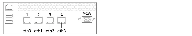
This page displays the list of all network adapters installed on the system, including virtual. Each adapter has the individual panel in the page.
The adapters in the web interface are related to the network adapters on the front panel of NetUP streamer:
|
|
The network adapter №1 on the front panel of NetUP streamer is the eth0 in the web interface, №2 – eth1, №3 – eth2, №4 – eth3 |
The following actions are available on the page:
1.Create a VLAN (virtual adapter)
Click Add VLAN. In the opened window select the Network interface, that you want to use for creating a virtual one, write the VLAN ID and IP address/mask, then click Save.
|
|
The VLAN name will be composed of the physical interface name and the entered ID |
2.Connect to IPTV Core
Click Change Core IP, then in the opened window, write IP address and click Save to connect to IPTV Core. As result, in the IPTV Core web interface, on the Connections page, should appear information about the connection to this server.
|
|
Change Core IP button is only present on non IPTV Core servers |
3.Assign IP Address to Adapter
Click Add alias on an adapter panel. In the opened window, write IP address/mask and click Save.
|
|
The list of all IP addresses assigned to the adapter is displayed on the adapter panel in the Aliases column |
4.Display adapter load statistics in graphic
Click Statistics on an adapter panel to see the statistic.
5.Set the main interface
Left-click on the IP address (Inet adress) of an adapter. In the opened window check the Main interface box and click Save.
|
|
The default main interface is eth0 |
6.Edit an IP-address or delete it
Left-click on the IP address (Inet adress or Aliasses) you want to edit. In the opened window change the IP address and click Save. You cannot delete Main IP or the last remaining IP address of the adapter.
|
|
The address assigned for the main interface is used for the component’s interaction and thus is absolutely crucial for the system’s operation. It can never be deleted |
7.Change the IP addresses range served by the DHCP server
Left-click on the IP addresses range in the DHCP server column on the panel of an adapter. In the opened window specify the required range and, if necessary, add static addresses, then click Save to apply changes.
8.Stop or start DHCP server
Click UP / DOWN on the panel of an adapter. In the opened window click OK to switch the server.
|
|
The UP / DOWN button is also the DHCP server status indicator |
9.Delete a VLAN
Click Delete VLAN on the panel of an adapter. In the opened window click OK to delete the selected adapter.
This page displays User routing rules and System routing table.
The following actions are available on the page:
1.Add a user routing rule
Click Add rule, then in the opened window, write IP address/mask, Gateway, select Network interface and click Save.
|
|
Automatic backup is made every day |
2.Edit or delete a rule
Left-click on a rule. In the opened window make changes and click Save to apply them or click Delete to remove the rule.
3.Show or hide the system routing table
Click on the Show / Hide button.
|
|
The system routing table is needed for correct system operation |
Use this page to change the access password.
|
|
Server admin password is used for SSH and FTP access |
This page displays the list of the system services and their statuses (started or stopped).
|
|
Left-click on a service name. In the opened window click Start or Stop to switch the service |
Use this page to set the server date and time, and select timezone. These features are only available for the IPTV Core.
The following actions are available on the page:
1.Set time manually
Click Set time, then in the opened window write Date and Time, then click Save.
2.Select timezone
Click Select. In the opened window, select timezone and click Save.
|
|
Set the correct timezone before uploading the license (see Licence), otherwise the system may work incorrectly |
3.Add an NTP server
Click Add. In the opened window write the address of an NTP server and click Save.
4.Delete an NTP server
Left-click on the address of the server you want to remove and click Delete in the opened window.
|
|
For each NTP server, you can see a synchronization status: Filed – the last sync attempt has failed; SYNC – the sync has been performed successfully; Reserved – this time server has not been used yet. |
This page displays information about uploaded licenses (components, numbers, expiration dates and restrictions). Use this page to upload new licenses.
|
|
Set the correct timezone before uploading the license (see Date and time) |
|
|
Make sure the new license is fully compatible with the old one before uploading it |
This page keeps info about the NetUP.tv system: product and firmware versions, build numbers of individual systems, information about the license and server hardware (CPU, memory, hard drives and network interfaces).
This page displays all the systems of the NetUP.tv. Each of the systems has a separate panel. The panel displays a list of systems with which interaction is possible. Addresses of interacting systems are links.
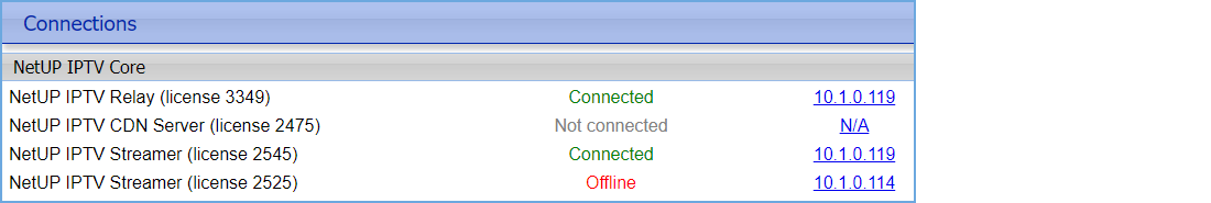
The following actions are available on the page:
1.Change a system address (server host)
Left-click on the system address you want to change. In the opened window write the address manually or click Auto detect to detect the address automatically, then click Apply to save changes.
This page displays disk space usage and S.M.A.R.T. and RAID condition report.
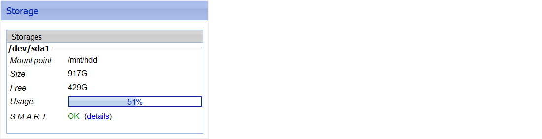
|
|
Click on details to see the detailed S.M.A.R.T. or RAID condition report |
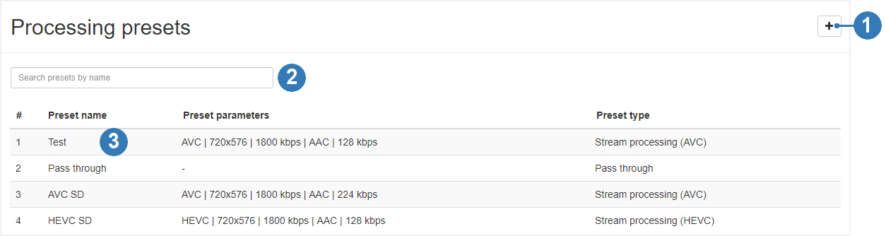
The following actions are available on the page:
1.Add a preset
Click on the corresponding button on the page. In the opened window select processing parameters you want to store in the preset and click Save.
|
|
Presets are classified into the following types: Pass through (pass the stream as is, without processing), Stream processing AVC, HEVC or MPEG-2. For all preset types except Pass through, you can configure video and audio processing parameters |
2.Find a preset
Enter the preset name in the search bar and the search results will be displayed on the page.
3.Edit or delete a preset
Left-click on the line with preset data you want to edit or delete. In the opened window change parameters and click Save or click Delete to remove the preset.
|
|
You can not change the preset type |
|
|
Changing parameters does not affect output streams that were configured using this processing preset. A set of preset settings is used only to quickly fill out web forms |
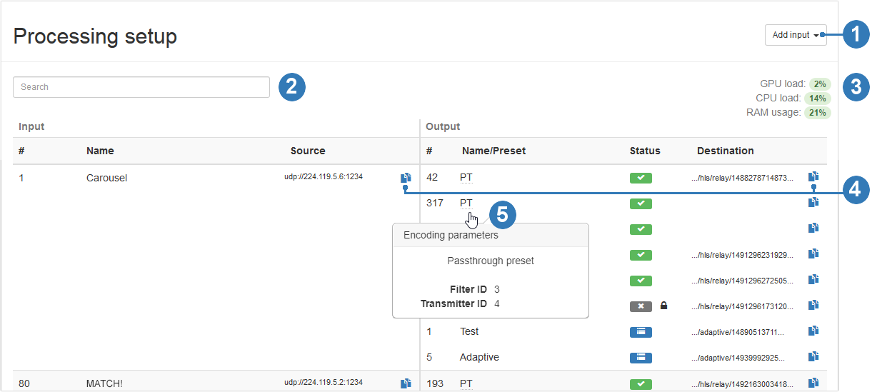
The following actions are available on the page:
1.Add input
Click on the corresponding button and select one of the options – from NetUP Streamer, from network video stream or from file. In the opened window, fill in the fields and click Save. After adding the stream, you automatically get to the Manage output streams page
|
|
Connect to the server via SSH and upload the video file to /netup/playlist/ before adding a stream from the file |
2.Find an input
Enter the input name in the search bar and the search results will be displayed on the page.
3.See a transcoder load
The transcoder load is displayed in the upper right part of the page.
4.Copy an input or output address
Click on the corresponding button next to a stream address. Data will be automatically copied to the clipboard.
5.See encoding parameters
Hover the mouse over an output name to show the pop-up window that contains transcoding parameters for the output.
 – Stopped
 – Error
 – Adaptive stream
 – Encrypted stream
7.Stop input, delete it or edit its parameters
Left-click on the line with an input data to open the Manage output streams page (read the description of this page in the next section). In the upper-right corner click one of the following buttons:
–Stop input to stop broadcasting all output streams configured for this input;
–Delete input to remove the input;
–Edit input stream to make changes.
8.Manage output streams
Left-click on the line with an output data. In the opened window make changes and click Save or Delete to remove the output stream.
You can Stop output stream (excluding an adaptive). Left-click on the line with an output data and click corresponding button in the opened window.
|
|
When the output stream is stopped, the interface displays the Start output button. Click on the button to restart broadcast |
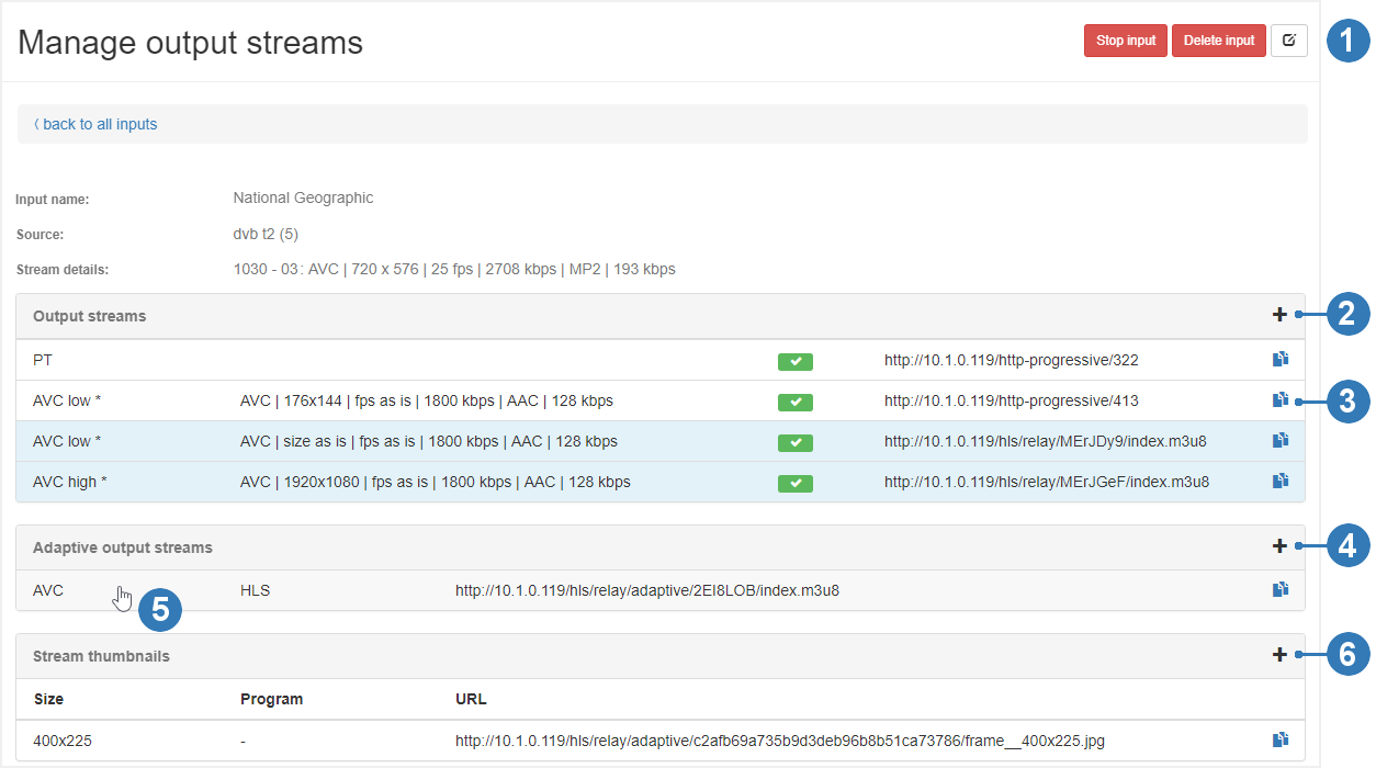
The following actions are available on the page:
1.Stop an input, delete an input stream or edit its parameters
Click on the corresponding button on the page to stop the input. If you stop the input, the broadcast of all output streams configured for this input will also be stopped.
|
|
When the input is stopped, the interface displays the Start input button. Click on the button to restart input. Restarting the input, you are restoring the broadcast of all output streams that worked before the input was stopped |
Click on the corresponding button to delete the input stream and confirm the action in the opened window.
Click Edit input stream to change its parameters, then make changes and click Save in the opened window.
2.Add an output stream
Click on the corresponding button on the page. In the opened window fill in the fields and click Save. The new output will displayed on the Output streams panel.
|
|
While adding the output stream, you can change processing settings on Video and Audio tabs. These changes do not affect the preset. |
3.Copy an output stream address
Click on the corresponding button next to a stream address. Data will be automatically copied to the clipboard.
4.Add an adaptive output stream
Click on the corresponding button on the page. In the opened window select streams you want to include in the adaptive stream, then click Save. The new adaptive stream will be displayed on the Adaptive output streams panel.
|
|
Before creating an adaptive stream, add the required number of output HLS streams which should be included in it. Use the corresponding button on the Output streams panel to add streams |
5.See the output streams included in an adaptive stream
Hover the mouse over an adaptive stream and the streams that are included in it will be highlighted on the Output streams panel.
6.Add a thumbnails stream
Click on the corresponding button on the page. In the opened window specify the Thumbnail size and click Save. The new thumbnails stream will be displayed on the Stream thumbnails panel.
|
|
The thumbnails with default size are used in the NetUP Android IP STB interface. |
|
|
Thumbnails are used in the TV channels menu, in the STB interface. If you do not add the thumbnails stream for an input, the STB menu will display a TV channel logo |
7.Edit parameters of an output, delete or stop it
Left-click on the line with an output data (including an adaptive and a thumbnails streams). In the opened window make changes and click Save or click Delete to remove the output stream.
You can stop an output stream (excluding an adaptive and a thumbnails streams). Left-click on the line with an output data and click corresponding button in the opened window.
|
|
When the output stream is stopped, the interface displays the Start output button. Click on the button to restart broadcast |
1.Open the Processing presets page (the Video stream processing group) in the web interface and click Add preset in the upper right corner of the page.
2.In the opened window set up settings for stream processing and click Save.
3.Open the Processing setup page (the Video stream processing group) in the web interface and click Add input in the upper right corner of the page, and select a stream type.
4.In the opened window fill in the fields and click Save.
5.On the Processing setup page, find the created input stream and click on it.
6.On the opened Manage output streams page, on the Output streams panel, click Add output.
7.In the opened window, select the created processing preset, if it’s necessary, edit video and audio setting for the stream and click Save.
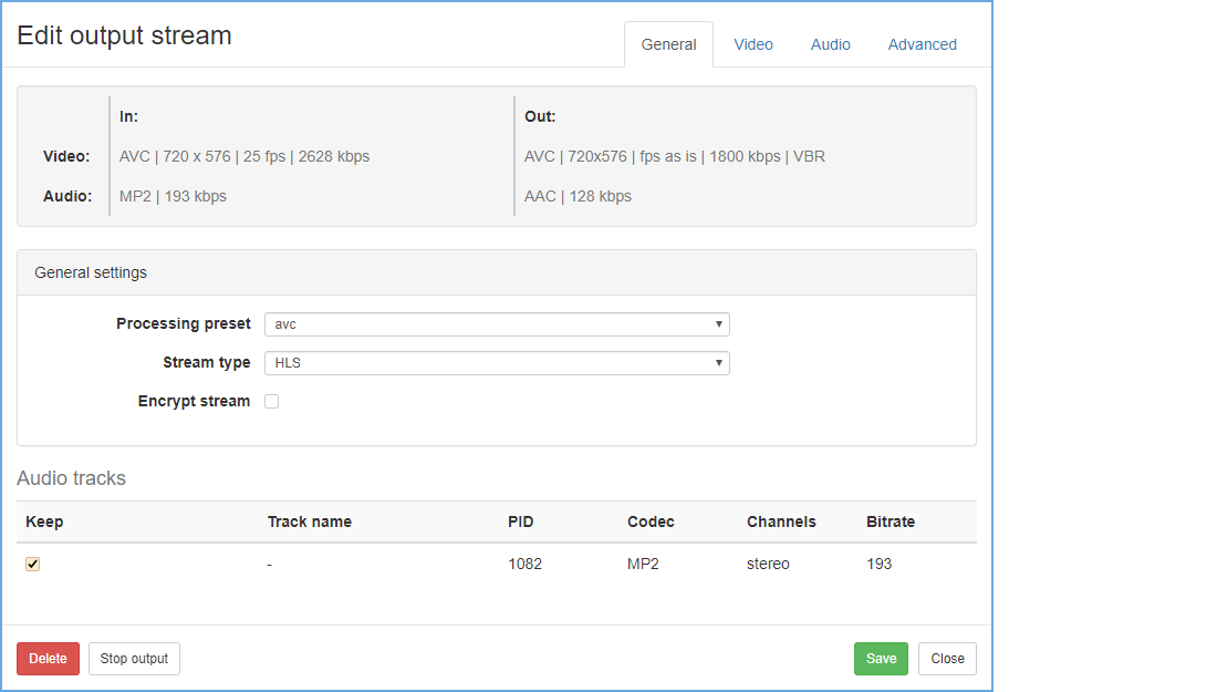
|
|
While adding the output stream, you can change processing settings on Video and Audio tabs. These changes do not affect the preset. |
 – Started